Stimulation Control Board
A controller for multichannel muscle stimulation at the biomechatronics lab!
In the summer before college started, I did an internship with the MIT Biomechatronics group, which is at the forefront of robotic prosthetic design. It turns out that the prosthesis industry is relatively small, so companies have little competition, and ultimately, incentive to improve their products in technologically meaningful ways (despite continuing to charge… a lot). Instead, Biomech, led by Hugh Herr, designs the new technologies for companies to be able to easily “upgrade” their old devices. Ottobock, for example, sells the Empower Prosthetic Ankle, which was designed in the lab and is now the most advanced prosthetic ankle in the industry.
The point is that the engineering that Biomechatronics does is important and has the capacity to improve the lives of thousands of people - and that’s why I wanted to be an intern!
First, you need a bit of an overview of the process by which amputations need to be performed in order to enable the cool stuff the lab is currently working on. If you don’t care about that, just skip until you get to the part about designing the board.
Amputations
The AMI
The Agonist-Antagonist Myoneural Interface (AMI) is a surgery designed by the lab to allow amputees to retain some of the ordinary biological functions of their muscles. Practically all muscles have an agonist and antagonist - your bicep and tricep, for example - to enable the the movement of your limbs. The overall mechanical reason for this is obvious, since muscles compress much more powerfully than they extend, but the more nuanced one is that each muscle can then feel the other, allowing one to effectively serve as a sensor for the actions of the other. This relationship, a result of both muscles working together, is something that your spinal cord leverages to accurately allow you to accurately control your muscles and have proprioception.
A good example of this is stiffening your arm in a certain pose - why doesn’t one muscle stiffen more than the other?
The problem with this beautiful biological structure is that it isn’t at all compatible with invasive human surgeries like amputations (sarcasm inteded). Traditional amputations usually connect residual muscle to the residual bone - something which is practically opposite to an opposing muscle (it’s not at all elastic and has no nerve endings to ‘sense’). In consequence, not only do the muscles in amputated limbs atrophy quickly (resulting in smaller and smaller residual limbs - this is expensive considering that one will need new sockets), but the muscle is fundamentally compromised such that it no longer produces similar electromyographic signals (the voltages your muscles receive from your spinal cord) as ordinary muscles.
The solution to this is the AAMI: a specialized surgery which retains the connection between muscles by tying the ends of their tendons together. This knot then rests on the bone, which is grinded into the shape of a pulley so that the muscles are still stretched. The result is that after surgery, amputees can still move their muscles while maintaining their physiological relationship, not only preventing them from atrophying as quickly, but also allowing them to preserve their characteristic EMG signal outputs.
Here’s a picture from the paper, which contains much more (graphic) pictures.

That’s the important part. The lab has also come up with a way to place electrodes for sensing and stimulation in the residual limb through an exposed connector at the end of the leg, but I think that’s less important for now.
My project
My supervisor’s project builds on the work of the AMI and EMG sensing for a novel robotic leg controller that works under neural control - amputees can move the prosthetic simply by… thinking about it, since it just picks up on the muscle signals from the muscles preserved by the AMI!
Although this is super powerful, it has a seemingly trivial limitation - it cannot provide feedback to the user. The human-robot interaction is open loop because the muscles which the robot is sensing aren’t being stimulated in response to a resistance on the robot. As a result, the person can only feel a resistance against the robot through the limbs around that which is being resisted.
That’s where my project comes in - building an interface which allows for simultaneous sensing and stimulating on multiple muscles. This has added difficulty in that stimulators are large, and even one is too large to be strapped to a patient (even for testing), so the interface needs to be able to ‘bit bang’ the stimulation.
Design
Here were the design requirements (DRs) for this board:
- Isolation between signal electronics and stimulation current (for safety)
- Switching speeds of up to 50Hz (this is the maximum frequency at which you can differentiate discrete changed in stimulation)
- Able to switch currents of up to 10mA at ~100V
- Lots of communication ports for expansion and future development (I2C, CAN, Serial, WiFi)
I was also requested to give this board a ‘test mode’ setup which would allow one to manually change the port for bench testing, so that resulted in a few additional features:
- Screen to show what it’s doing
- CLI interface (this actually wasn’t requested, I just did it for fun)
The end goal is for this device to a standalone controller for any stimulation that will occur on a user while testing. That means that it needs to be portable and have enough computing power to be able to run simple logic.
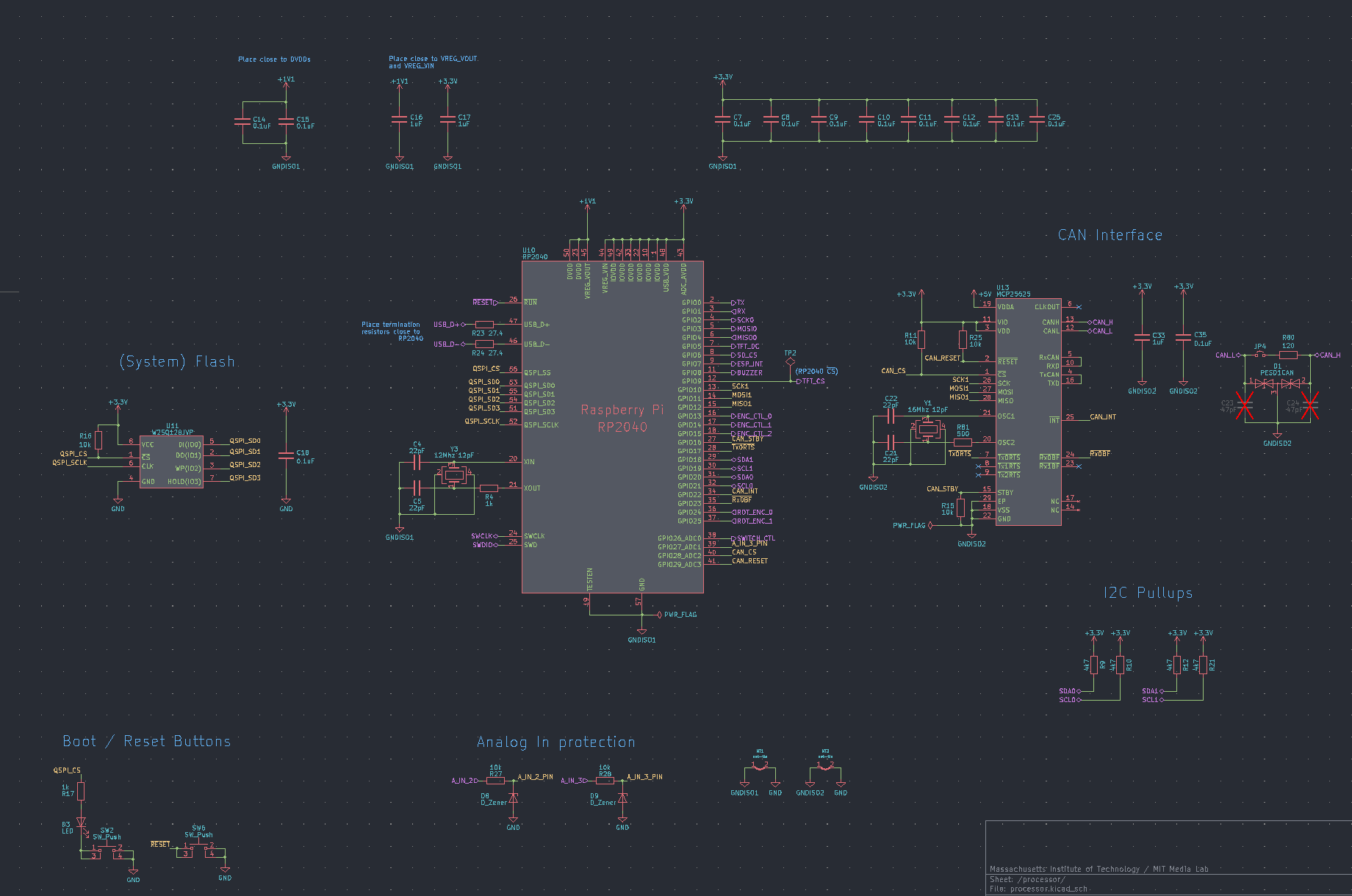
Schematic
Since I’ve been hearing good things about it, I chose the RP2040 microprocessor. What’s super cool about this board is that is has configurable IO, which made routing much easier, two I2C and SPI ports, it’s easy to use (it only needs external flash and a crystal), and is dual-core with FreeRTOS support. Although it was definitely overkill for this project, FreeRTOS is something I’ve been wanting to learn for a while, and implementing that with two cores would make this thing a beast.
As for communication bus capability, I chose:
- MCP25625 for CAN
- ESP8266 as a coprocessor to the RP2040 for WiFi support (specifically, the board needs to interface with an MQTT server)
- The RP2040’s I2C ports
For isolation on each stimulation port, I chose to use G3VM-351GL optical relays. I’d never used optical components before, so finding these was super cool! They’re also super easy to use, since you’re basically only turning on an LED. The board has 16 of them (eight ports * two channels per port), and they’re each driven by small N-Channel mosfet.

Each of these mosfets is driven by a 3:8 decoder to conserve pins on the RP2040:

Slap on a usb connector, a small LCD display, and a rotary dial (for manual port selection), and you’re finished!
Layout
I put lots of time into the layout to make the board as compact as I could.
The first part I tackled was the switches. Although it may have might be a little overkill, I isolated all the switching components from the rest of the board without an underlying ground plane to make sure that they wouldn’t be inducing (or get induced) current, since I was concerned with the switching not being fast enough (or some parasitics screwing with the signal). Not adding a ground plane under everything was motivated by trying to prevent capacitance on the stimulation traces. I also impedance-matched each pair of channels so that the high and low stimulation ports would never be out of phase. The end result looked like this:

It’s difficult to see, but the optical relays surround a JST-GH upright connection (which goes to the eOPRA connector for the patient) and have their little mosfet circuits underneat them on the otherside of the board. The squiglies are a result of the impedance matching.
The next area of focus was the microprocessor. Although it probably was, again, a little overkill, I added star-point grounding between the main board and each of the switching circuits. The idea is that you locally bypass high frequency noise for isolation, and then connect that local ground to the rest of the board at the same point as other circuits and through a small trace so that you can:
- Limit the current flow in each circuit to isolate noise and burst currents (totally not applicable here)
- Prevent large polarities in the ground plane at any point (which is why all points join ground at a single node - this is the “star point”)
Doing that and routing the microcontroller and CAN controller (which also has a local ground plane since it has a crystal) looks like this:

… and that, plus a bunch of other routing, looks like this!

If you’re curious about where the display goes, it sits on top of everything on header pins (I chose to use an adafruit module for simplicity). You can see this in the cad model for the board, which took an obnoxiously long time to make:

Fabrication
Soldering everything together took a long time, but it was definitely worth it. I used a reflow oven for the small smd components (mainly the QFNs), but had to correct some of the joints manually (doing this on the RP2040, which has 0.4mm pitch, was a truly character-building experience). It took a little while, but the end product was definitely worth it. I think this is the coolest-looking board I’ve ever made:

and with the screen:

The dial hasn’t been added yet, only because I haven’t had to use it.
Conclusion
That’s it! The next post will be about the software going into this thing (as well as what it can actually do… with a patient!).
Mistakes
Remember how I was talking about star point grounding? Well, in doing that, I made a mistake with my ground planes - my local planes were on the back of the board, while the components which connected to it were on the top. This is bad because ground planes actually provide two important functions:
- An uninhibited ground source (which means convenient routing)
- A reference point for capacitance between the ground pland and the components using it.
Since I have a four layer board, I had another ground plane (and power plane) in between my local plane and its components - this means that those components are way more susceptible to noise than they otherwise would be. That said, given that everything here is digital and there’s little opportunity for induced noise, it probably isn’t a problem (and I probably could’ve gotten away without star point grounding at all).
As far as I know, that’s it for now - no dealbreakers!
I must add that it also feels good to be writing posts again :D