DC Link Capacitor Sizing for Traction Inverters
One of reasons for writing maple was to get a better idea of how to design custom inverters for the motorsports race car. Since we’re designing the board now, the first obvious use of the simulation is sizing DC link capacitors since this is difficult to calculate by hand. For a mobile traction inverter, bulk capacitance can take up to 50% of the volume and can become quite expensive, so it makes sense to minimize, but it’s important to have a large-enough capacitance to prevent exessive bus current ripple (which leads output torque ripple - the actual problem).
Equations
I’m following this paper for this analysis. It does the hard part of deriving the equations, but I’ll give a little recap of their results so it’s a little more clear what’s going on.
Basically, we take the rms current flowing through the switches of the three h-bridges together as the sum of the DC / average and AC currents and assume that the capacitors are responsible for providing all of the AC rms current:
\[I_{C, RMS}^{2} + I_{avg}^2 = I_{rms}^2\]The paper does the hard part of deriving these individual components:
\[\begin{align} I_{RMS}&=I_{N, RMS}\sqrt{ \frac{2\sqrt{ 3 }}{\pi}M \left( \frac{1}{4}+\cos(\phi)^2 \right)}\\ I_{RMS}&=\frac{3}{4}I_{N}M\cos(\phi) \end{align}\]Which simplifies to:
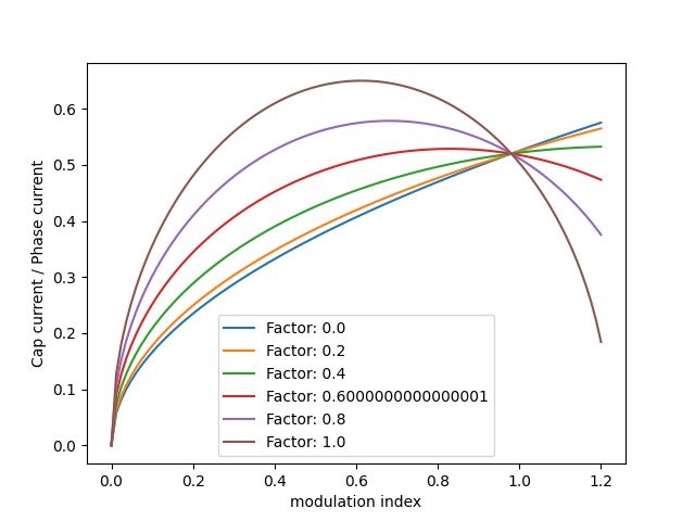
\[\begin{align} I_{C,RMS}^2=I_{N,RMS}\sqrt{2M\left[ \frac{\sqrt{ 3 }}{4\pi}+\cos^2(\phi)\left( \frac{\sqrt{ 3 }}{\pi}-\frac{9}{16}M \right) \right]} \end{align}\]Where $M$ is modulation index, and $ \cos{\phi} $ is power factor. Graphing for a variety of power factors and modulation indices gives a good idea of the capacitor stress relative to the bus stress:

Since modulation index changes as the car drives (depending on output torque / backemf), I decided to use the worst-case modulation index for all computation. For convex regions of the function between $ (0, 1) $, the maximum is given by
\[M = \frac{2(\sqrt{ 3 }+4\cos(\phi)\sqrt{ 3 })}{9\cos(\phi) \pi}\]Simulation
One of the reasons the hand calculations are difficult is because you need to consider the effects PWM (which increases total harmonic distortion and decreases power factor), but simulating PWM is easy1, so the model should be able to accurately provide per-phase current and voltage information. Then it’s pretty straightforward to calculate power factor; real power is the average instantaneous power, and apparent power is the sum of the RMS power.
I simulated at the maximum torque outputs using the following parameters:
L_dq = (0.24e-3, 0.12e-3)
R_ipm = 0.135 * np.eye(2)
ipm_pm_flux = 0.0165
inertia = 0.0274 # kg m^2
motor = SalientMachine(L_dq, R_ipm, ipm_pm_flux, inertia, winding="delta", pole_pairs=10)
inverter = FOCInverter(0.5, 1, 0.5, 1.5, (-10, 10), 350, 5000)
inverter.command(10.59, 39.61)
inverter.drive(motor)
For a maximum capacitor RMS current ripple of ~5.8A, calculated with the equations above. Allowing a voltage ripple of 5V and assuming switching at 10Khz with a 50% duty cycle2, the required DC bus capacitance is only $ 58 \mu F$! This might sound like super little, but the commercial motor inverters we’re using for the 2025 competition have a bus capacitance of $ 75 \mu F$, so this definitely seems plausible. Calling our inverters “traction inverters” is a bit of a misnomer since our motors are tiny compared to a real car… but it’s still a racecar!
I’d really also like to be able to simulate core losses (since current ripple should have a big impact on that as well) but haven’t gotten around to doing that yet and kinda doubt the accuracy I’ll be able to get with the AMKs (I don’t know anything about the internal materials). There’ll be a post coming soon about that.
-
PWM is implemented by sampling, calculating the duty cycle based on a sawtooth reference signal between the lowest and highest switching voltages, and holding at the high / low voltage value based on that duty cycle. This is basically how a real microprocessor does it with timers. ↩
-
I realize that this would mean the modulation index isn’t at worst case, at least that assumption provides a bit of margin. ↩