Race car Avionics
As you may know, I’m on MIT Motorsports. We build an electric race car to compete in the formula sae electric and hybrid competitions in Michigan and New Hampshire each year. Last year we did alright (~20th at Michigan and 4th at Hybrid - things were rough for the team coming off of covid), so this year we hope to design an absolute unit of a car so we can make top 5 at Michigan.
A quick aside; last year, our car was actually pretty good, but very heavy (we were too conservative on a lot of things). This year, we’re prioritizing weight, which motivated a composites team to investigate CF design. Electrically, we’re switching to independent four-wheel-drive - that is, one motor at each wheel - which should give us a lot more power.
This year, I’m working on the LV / Control electronics for the car. Since a lot of the electronics from last year predated most of the members of the team (designs were from before covid), our goal was to fully redesign everything in order to fully understand the system while improving a few key shortcomings of the previous design. Aside from the rules-required electronics, the goal was to improve:
- Computational Speed
- High-speed telemetry
- Modularity
- Data Acquisition
Also, the “mega” part of MegaLV (mega low-voltage) comes from the fact that a lot of the functionality of megalv was broken up into different boards / boxes distributed throughout the car last year. Since that resulted in a lot of annoying problems (more boxes to seal, more wires to order / connect up, etc.) we wanted to put it all together onto a more compact set of boards that fits in one box. Although I’m not going to talk about how we debugged these boards or share more information on how they work (after all, we’re using them to compete with other schools!), rest assured that all functionality here has been tested and validated - everything works.
Architecture
I decided to break up what used to be a single “vechicle control unit” (with builtin telemetry and some car-wide power regulation) into three boards - a backplane to manage and report power distribution throughout the car, a standalone telemetry board, and a vehicle control unit that consists only of rules-required hardware and some compute. This way the individual boards could be smaller, making them hopefuly easier to debug (especially for software people, who typically are only debugging one part of those boards).
Here’s a diagram of how power is managed:

And how the three canbuses throughout our car connect onto megalv:

Design
Here’s what last year’s vcu looked like:

It’s quite a chonker. Here’s this year’s vcu:


It’s around 1.5”x1.5” and has a faster mcu (STM32H7 vs STM32f4). Other interesting things about this board:
- Has three CanFD transceivers, one isolated for noise immunity to inverters
- IsoSpi interface for connecting to a custom LV battery
- Some thermometers
- Controls our shutdown loop (rules stuff)
Shutdown loop is a hardware loop of wire that ensures continuity on critical electrical interfaces of the car, like shutdown buttons and brake sensors. It also powers the main contactors, so the idea is that if any part of the shutdown loop breaks that the contactors will close (and thereby shutdown the HV system). That’s what the six SSRs at the top of the board are for.
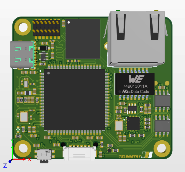
Here’s telemetry board:

And the bottom:

Last year, our telemetry consisted only of an RFD900 LoRa radio. Although this is basically the best commercial one you can buy, it’s still too slow for the amount of data we want to offload, and can also be a bit spotty sometimes. This year we want to use point-to-point wifi, hence the ethernet interface.
For realtime caching, we’re using eMMC / Sd card. Since eMMC a 4-bit parallel bus, we can get transmission speeds of up to around 100MBps with it, which is plenty fast!
Interesting things about telem board:
- 100Mbps (fast) ethernet
- eMMC / SdMMC
- STM32H755 (dual core)
Here’s the first revision of the backplane, possibly the simplest board:

I really disliked this layout since it wastes so much space, but I was on a bit of a time crunch. During winter break I made a new one that’s more space optimized:

The VCU and telemetry boards interface with the big samtec connectors, so the full arrangement looks like this:

And all soldered up:

It’s smaller than my phone!!
Backplane connects to the main harness of the car and distributes proper connections and power to VCU and Telemetry board. It also does all the power management for the rest of the car - the stuff on the left is basically a bunch of hall current sensors and mosfets to regulate the power draw of the rest of the LV system outside MegaLV like the cooling system.
That’s most of our control electronics for this year! Overall, not too complicated, but it was getting to design with some peripherals I’d never used before (like ethernet and the eMMC stuff).