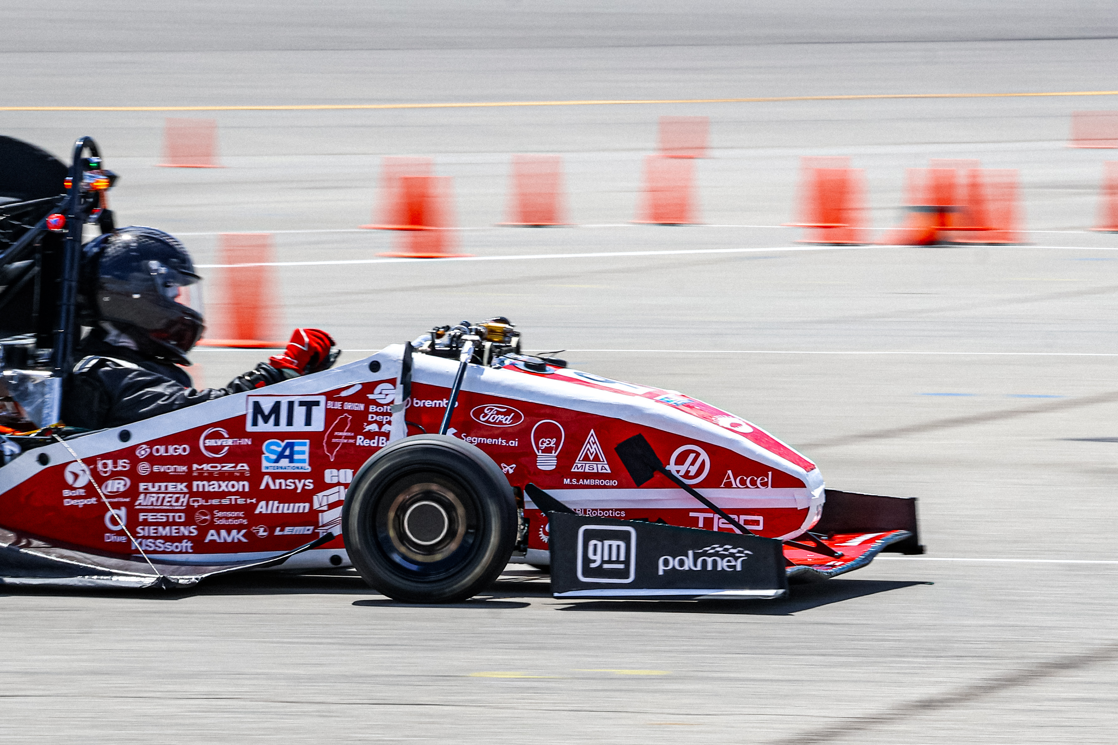
I was the electrical lead for MIT Motorsports, 2026. Unfortunately we didn’t do that well (dnf endurance because our aero floor was scrapping the ground) but this was by a large margin the best car the team has ever made. It also has the best electrical system the team has ever made.
Quick specs
- All custom boards (except inverter, but we were so close!)
- STM32 suite
- Custom bms
- Canbus, ethernet for high speed data acquisition
LV
Aggregators
The LV system was similar to what I designed for 2025 - there were a few minimal changes for quality of life (like adding efuses to backplane). The main improvement was redesigning our data acquisition network. Previously we had a bunch of ‘sensornodes’ strung in a canbus that wrapped around the whole car, which was both a wiring nightmare and resulted in communication problems (once we got past around 20 devices we had weird SI problems and incessant bus conflicts). The solution to this was switching to a star-point communication network with data ‘aggregator’ boards installed in the front and rear of the car. Each aggregator has three local canfd networks, communicates with our ‘critical’ bus (used for critical sensors like pushrod strain gauges), our ‘sensor’ bus (for useful controls sensors we could afford to lose while driving) and a 100Base-T1 link (for high rate measurement and later analysis) that routes to a wifi antenna.
Aggregators are super cool because they allow us to collect data at the maximum canbus throughput (8Mbps) on each local chain (24Mbps total) and they send it straight to our local ground station. They also have sd cards for temporary local storage.
Ethernet is ac coupled, so it’s trivial to support power over data lines, which would allow you to reduce the wire count to each board by two. We didn’t end up implementing it (“too sketchy” 🥴) but aggregator technically supports it with a big differential mode choke. Main input power limitation comes from saturation current here, so max allowed power draw of aggregator was around 20W. There are efuses on the input power lines (and output power sources) to control this.
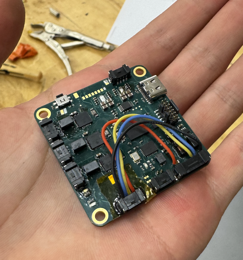
Picture of aggregator, after someone broke a connector + pads off one. Wires are going to a new connector epoxied to where the diff choke normally goes
The ethernet switch in the back:
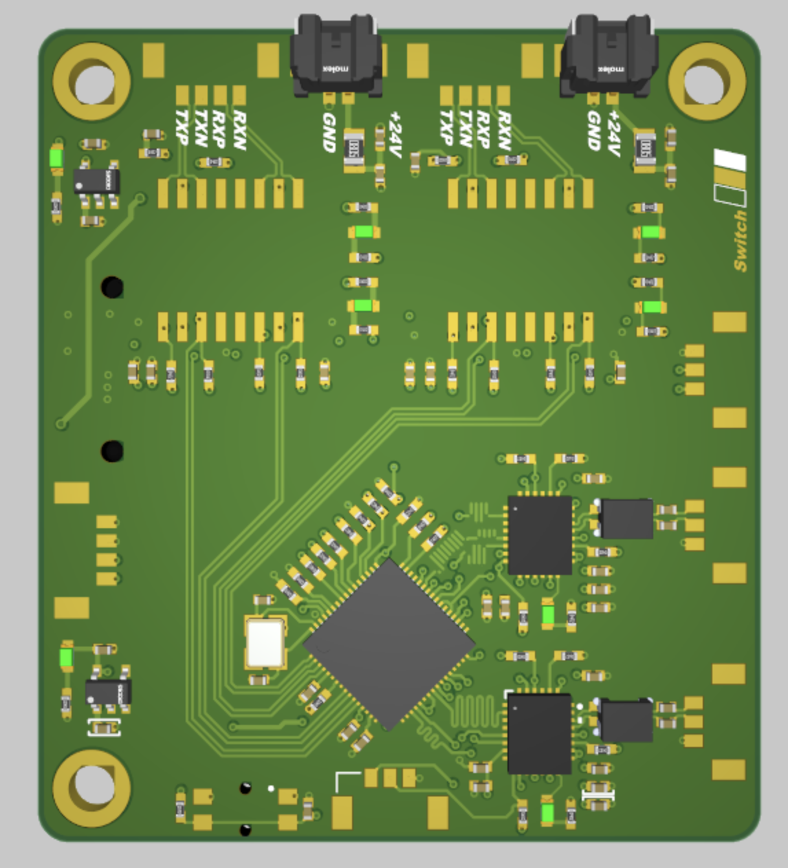
The switch has two 100Base-T1 ports and two 100Base-T ports. You’ll notice that there are no RJ45s though - these get routed off the connectors at the top to a separate microlock-to-RJ45 converter board. Ethernet can tolerate really high insertion loss, so ‘vibe’ engineering like this is fine.
Harnessing
The EE lead is the central system architect for the system, so a natural responsibility is harness design. This required a lot of interfacing with the mechanical team and is generally tedious to do - you need really good attention to detail or you’ll mega-screw future you. The car has around 8 important harnesses. They are mostly point to point, but the one that connects the core avionics system to the front of the car has a few branches and is the most complex:
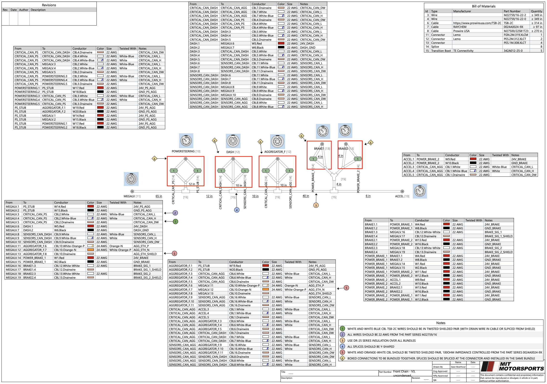
Even though ethernet is pretty robust, I didn’t skimp out on the ethernet wiring - we used 100Z diff controlled impedance twisted pair (10$/foot, insane) throughout front chain for the 100Base-T1.
I also got a Lemo sponsorship, so we used their M-Rugged series connectors everywhere, which are super nice.
HV
Inverters
This year Liong led design of our custom inverters. They work, but were finished too late to actually make it on time for competition. Check his pages out for techncial details!
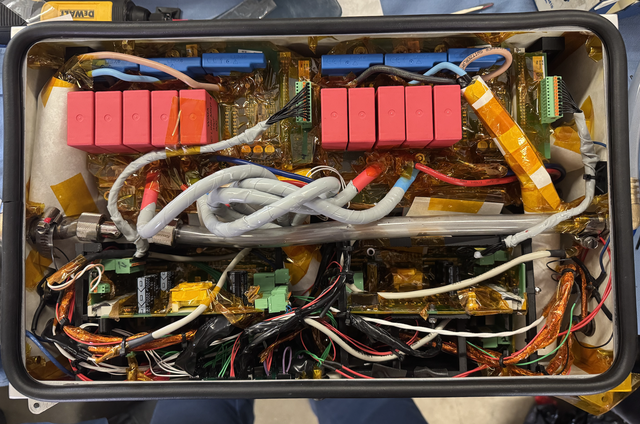
Instead we again used AMKs that we repackaged in a custom box since they are super large stock. The install was possibly the most horrible, gut-wrenching install process of anything I’ve ever had to put together. It took four of us around two weeks to finish and looks incredibly sus. The silicon tape and nomex were doing serious work to get this thing to pass the HV-LV insulation rules, and don’t get me started on how frightening the water cooling is in here.
Battery
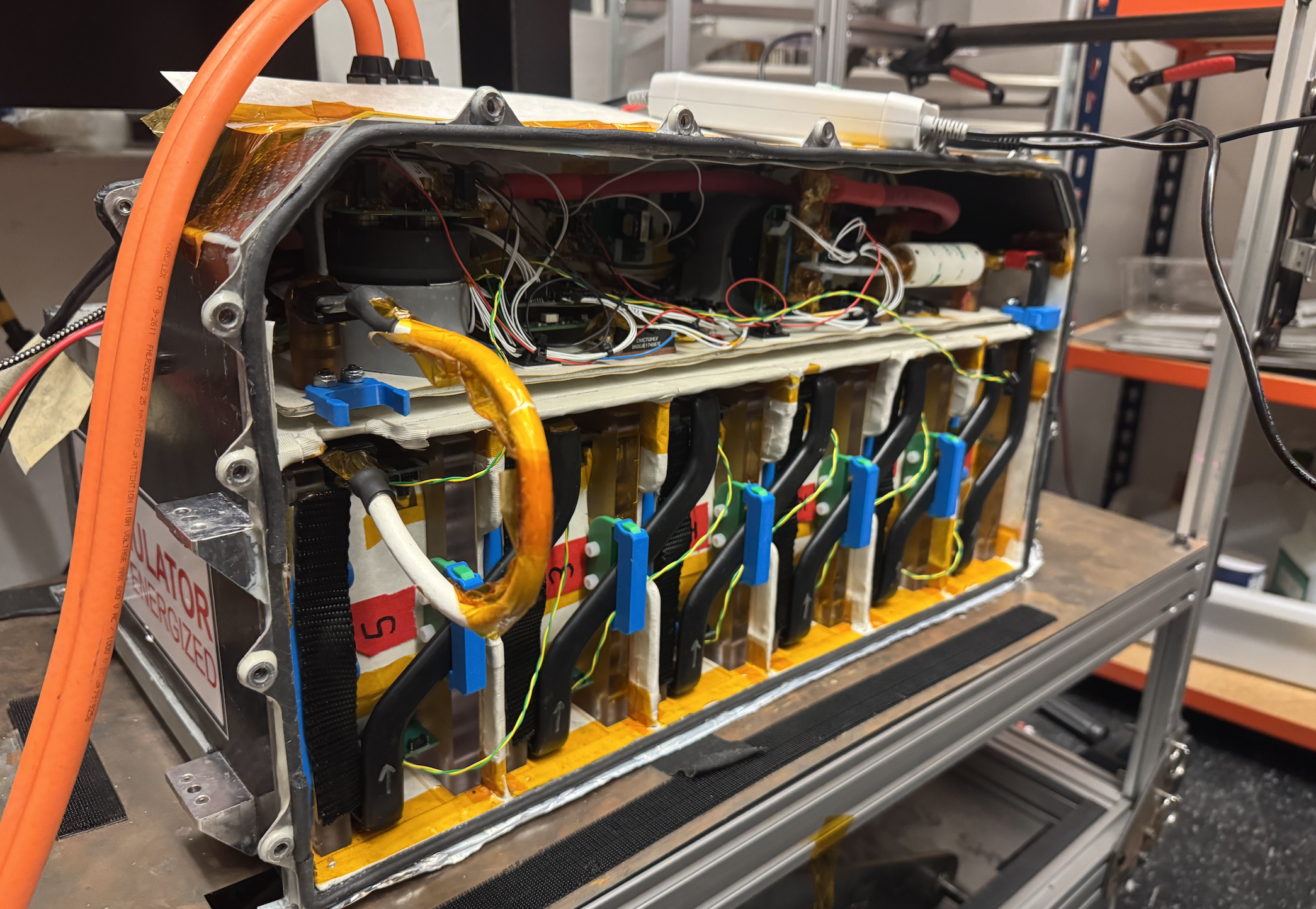
This year our battery was completely redesigned by Mia, Ramiro, and Max, who did a killer job. It’s the most compact and lightest battery (40kg) the team has ever made, thanks to Wenyu’s work making the structural CF for it.
Here’s a picture a picture of the inside of the battery from when we had to do some work on it. Wiring was later cleaned up:
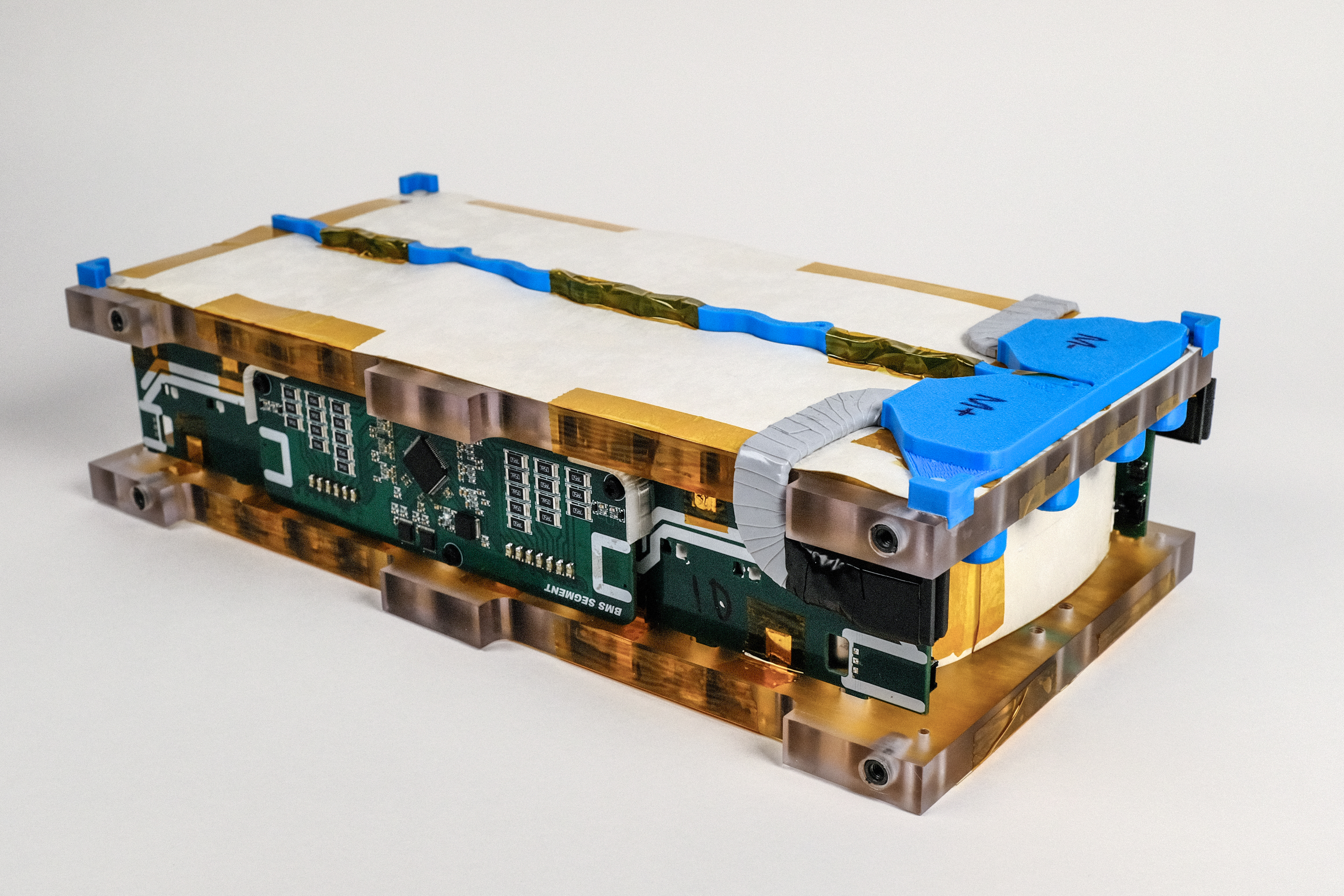
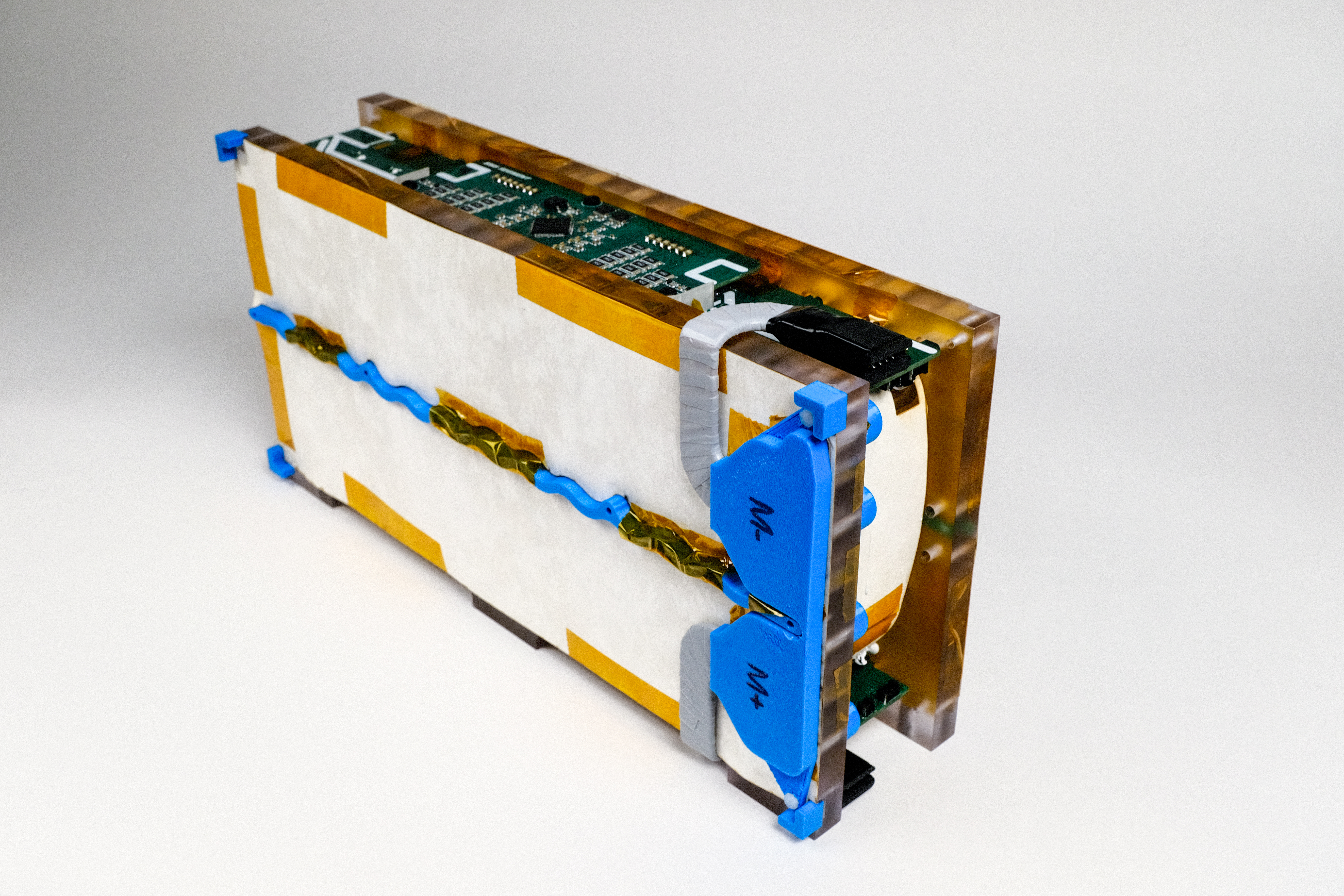
EE side was making the most compact BMS ever for it. From an electrical perspective, the ADBMS6830 bms controller we use is pretty1 easy to use, so the challenge became packaging it well. Each half of the six modules in the battery have a small interface ‘carrier’ that has a cell tap for each series count in the pack. These get routed to a ‘segment’ board which is the BMS for that section of the total pack. Carriers are permanently installed in the pack while segments are removable in case something breaks.
I found some ultra-low profile (6mm mated) smd headers from weurth that allowed us to stack our BMS boards really tightly:
Latchups
The biggest problem we had on the EE team was stopping our BMS chip from latching up. This was a huge problem that we found fairly late: sometimes on precharges the adbms responsible for managing the lowest cell count would latch up, frying the upstream LDO and dropping our communication link. We ended up solving this for michigan, but I’ve had to explain the problem so many times over the month-long, sleepless campaign I spent trying to solve this that I’m not going to explain it here. If you’re interested, you can read the recap I sent to the team here.
Other stuff
People are often curious about what build team leads actually do. Are they just yelling at people? Are they just redoing other people’s work? Have they grown positivey from this experience, either technically or in leadership?
Eventually I’ll write a post on mind about my thoughts on this, but to state it plainly, here are some of the things I did:
- Architected the full system, defining what the EE system looks like, where it goes, how it connects, etc.
- Reused a good amount of stuff from the previous year, which I designed a lot of (if it works, why fix it? I made it!)
- RE for all EE system interfaces with other teams; countless hours of running around talking to meches, packaging meetings, and scrutineering
- Design reviews on all submember boards
- Ordered all the boards (shocking amount of work since there are like 25 unique boards)
- Made BOMs we sent out to be assembled
- Designed most of the new boards this year (when shit hit the fan and needed to be redone, that was me…)
- Designed the BMS boards, with help from Sam
- Designed the aggregators and switch
- Designed the external car harnessing, made some of it
- Made all the HV harnessing
- Made some (like 10% maybe) of the external LV harnessing
- Soldered a good amount
- We only get components assembled if they are fairly cheap and available at JLCPCB. Unfortunately this doesn’t include many of the QFNs, some of the larger LQFPs, and anything else with a weird footprint. I’ve soldered hundreds of these
- Packaged a bunch of stuff in boxes
- Lots of debugging, like leading the latchup problem described above
- ~30% Boring EE rules stuff, like document submissions
- So much more random stuff, like installing / fixing the cooling system in the inverter box, getting boxes to fit, installing stuff on the car, showing people how to do stuff, etc. the most tiring and least flashy / exciting part
- Built lots of character!
I got a lot of help, on multiple occassions, from a few key people:
- Theo, our software lead - who saved me from my responsibilities countless times while I was crashing out
- Max
- Ramiro
- Mia
- Sam, the 27 EE lead!
- Nerissa
- And others!
Now, onto a glorious year retired from the team!
-
Big asterisk as I found out late in the year ↩