Muscle Stimulator Part 1
This summer, my main goal is figuring out how to make a mobile muscle stimulator with “blanking” capabilities. Here’s roughly how I arrived at this project:
Forword: I need to thank my lab mentor, Chris Shallal, for helping me out on this project, especially on the human-bio side of things. He’s the reason I didn’t accidentally electrocute myself :D
- Our lab is inventing super cool surgeries that allow us to provide feedback to amputees via controlled muscle contractions within their limb.
- A lot of research has gone into neural prosthesis control, which uses electromyography (EMG). Those control schemes are based on measuring a the natural voltage across your muscle during contraction. Won’t stimulation mess that up, since you’re basically injecting charge? (Answer: Yes)
- We have an awesome portable sEMG platform that we can use for testing our patients’ walking capabilities. Is it even rated for stimulation voltages? (Answer: No).
- Is the stimulator that we have (the only one that’s FDA approved for research) portable? (Answer: No)
- Do we want our patients to have a tether attached to them for stimulation only? Am I concerned about the integrity of the stimulation waveform (stimulation is roughly a 1Mhz biphasic squarewave) if we do this? (Answers: No, Yes)
- We should make a mobile muscle stimulator.
That’s basically the gist. The goal is to design a small multichannel (I’m currently aiming for 8 channels) muscle stimulator that can act as a “hat” for the sEMG board in order to be able to allow us to sense (via EMG) and stimulate a muscle at the same time. Why would you want that? Well, I talk about it a bit in my switcher board post, but the main idea is for the prosthesis to be able to relay forces / pressure against it to the amputee by inducing force / pressure on the muscles that would be feeling that. When a leg prosthesis hits something, for example, most users will feel the resulting forces in their hip (since they don’t have a leg anymore). The AMI surgery preserves the muscles in their leg and allows us to stimulate them so that users can “feel” that hit. The “sensing” part of the story comes back in when considering how the prosthesis is controlled - using EMG. This relies on measuring the voltage across the muscle the user preserves in the AMI to drive the prosthetic leg in the first place. Since that runs on a tight sampling frequency (I’ll go into why this important a bit later) it’s a bit tricky to get the stimulation, which charges your muscle, to work with EMG, which aims to measure natural charge buildup rather than the artificial stimulation charge. This makes filtering stimulation artifacts / noise out of the EMG a core technical goal for this project. I’ll get more into it later.
Stimulator Design
I’m trying to make a Functional Electric Stimulator (FES). If you’ve heard of a TENS (transcutaneous electrical nerve stimulation) machine, this is basically the same thing, except designed for muscle contraction. That means it can stimulate at higher currents, and usually, with more precision than commercial TENS devices. There are definitely TENS devices that can contract your muscles but those are kinda the border of the two. Mine is going to be configurable though (and have some more safety features…).
This is what the stimulation waveform is supposed to look like:

It’s biphasic because it stimulates both positive and negative current, and asymmetric because the magnitudes of each are different.
I also forgot to mention that contraction amount is a function of the charge injected in the muscle. As of now, the most charge that can be used to stimulate for research (as regulated by the FDA) is 30mC I believe. That’s what makes the biphasic aspect of this good, since we can maintain net zero charge in the muscle by making the integral across a waveform period 0, and why we need current control, as opposed to voltage control. Charge inbalance can lead to fatigue and skin rashes.
For us, the stimulation parameters are roughly:
- D: 200uS
- W: 100uS
- The unlabled positive time period: 2mS
- f: ~50Hz.
Not too bad.
The actual stimulation current depends a bit on the person, but in the average muscle, vibration / feeling occurs around 1mA, and contraction occurs around 10mA with this waveform. Things start to hurt past 15mA, and damage starts to occur at 30mA. That said, patients sometimes have completely different responses (some start to feel vibration at 10mA).
Research
I started off reading a few (actually it was a bunch, but as usual, only a few were actually helpful) papers on stimulators to see what current circuits existed for this kind of stuff. Muscles are typically modeled as a bulk resistor in series with a parallel resistor / capacitor arrangement:

In practice, we’ve found Rs to be accurate, and Rp to range from very low to around 2kΩ as well. This means that at a maximum stimulation of 30mA, a maximum muscle resistance of 4kΩ would require… a 120V drop! Keep that in mind as you look at these designs.
Most stimulators I found in literature were constant voltage controllers (again, bad because the current / charge then depends on the muscle impedance). These are some of the more promising current controllers I found… and why I didn’t like them:

- This is actually a constant voltage controller. Practically all of the ones I found were a derivation of this circuit (this particular one being the most complex)
- Although calculating through this circuit isn’t too bad, there is no negative feedback component that could remove variations due to temperature (transistors are pretty susceptible to this)

- This is a cascode current mirror, with the current drive set by R5. This makes it difficult to change the current dynamically
- There were other current mirror designs, but I couldn’t really see the reasoning behind using a charge pump. The use of mosfets stuck with me, however…

- A modified Howland current source with a low-side op amp. The benefit is that it’s easy to control current drive (you just set Vin).
- Since this needs to (as calculated above) drive up to 120V, you need a specialized power op amp. In general, as the power requirement for op amps increase, the other parameters, like slew rate, offset voltage, etc. get worse… which means that you need a really specialized op amp. That’s expensive. The one this paper used is $250!! And you need two of them!

- A really cool charge-pump-esque circuit that can drive both positive and negative voltages. It took me a while to understand what was going on here. It’s really a beautiful circuit.
- This circuit was designed by five graduate students / professors working together. If I made a mistake recreating this, I wasn’t sure if I could understand how to fix it. I also thought that things could be simpler.
That said, reading all those papers led to some pretty concrete design requirements:
Designing
The real crux of the problem is figuring out how to create a varying voltage that adapts to the muscle resistance. Creating a constant current source is pretty simple:

Assuming that the battery (I couldn’t find a voltage source symbol) is a high impedance output and $ V_{DD} $ can change to suit $ V_{DD} = \frac{V_{Batt}}{R_{11}} R_{muscle} + V_{Batt} $, the current through $ R_{muscle} $ is just $ \frac{V_{Batt}}{R_{11}} $. How do you get $V_{DD}$ to change though? This is where mosfets come in. In saturation mode, mosfet $ V_{DS} $ can basically increase arbitrarily to satisfy KVL regardless of $ I_{D} $ (as long as $ I_{D} $ doesn’t put it in the cutoff region). By sticking a mosfet in here, $ V_{DD} $ can stay constant, and with an op amp, the gate voltage can be easily controlled:

The drain current can now easily be set with the battery voltage, and the op amp provides negative feedback on the current through the load path - if $ V_{GS} $ is too high for some reason, the increase in $ I_{D} $ will increase the voltage on the inverting input of the op amp, decreasing the output voltage, and thereby decreasing $ V_{GS} $ and $ I_{D} $. R25 helps with leakage current.
The main benefit of this design is that it’s pretty simple and super easy to change the current drive. $ I_{D} = I_{Stim} $ is still set by $ \frac{V_{Batt}}{R_{11}} $.
I sat on this for a while, but still a bit worried about its success, looked around for some traditional constant current drivers. And flabbergasted, in a TI application note, I found this!

The only difference is C1, which they say is used to attenuate transient response. This makes sense, because mosfets have a gate-source capacitance that can cause ringing. C1 closes an RC circuit between $C_{GS}$, R1, C1, and R2, which means that you can control the transient response more easily with any of those components (preferably C1 and R2, since R1 is for limiting the transient gate current).
Also, a negative version of this can be made simply by making $ V_{DD} $ negative and changing the nmos to a pmos.
Simulation
I simulated the circuits in pSpice, copying the values for C1 and R6 from the Ti page. You can’t really simulate these unless everything is identical to reality, so the plan was to tune these on the actual boards I ordered.
Here’s a DC sweep on the drive voltage, measuring the load current (negative version, although the positive one is identical but flipped):

And here’s a transient step response of the positive version:

Obviously the transient simulation can’t really be trusted (I don’t have any parasitics modeled and I’m using different components anyway) but I wanted to get some confidence that system stability was somewhere in sight. The DC sweep was extremely satisfying, since that’s exactly what I need.
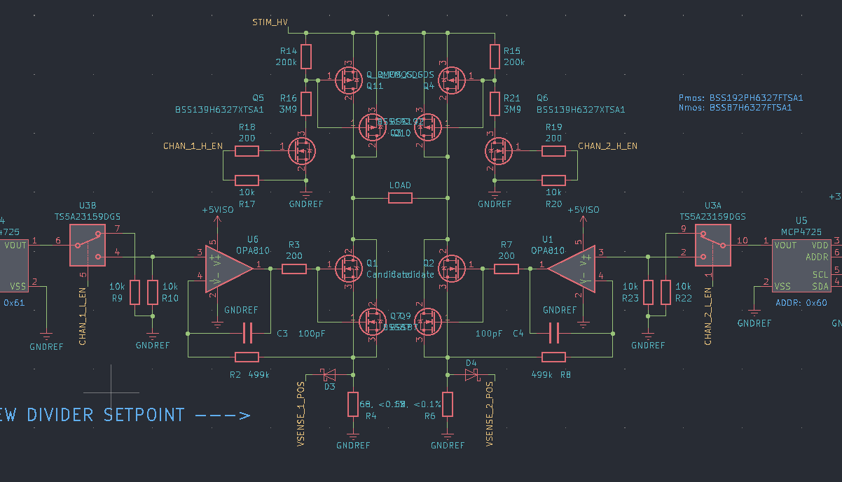
To make the waveform easy to control, I added an analog switch on the output of a small 12 bit DAC so it’s just a matter of outputing PWM. This is what the driver looked like when (almost) complete:

Negative source
To achieve the negative current source, I originally thought about making a negative version of this (hence the negative simulation), but I quickly realized that this didn’t really make any sense. All you really need is the same driver, but driving the load in the opposite direction. And if you’re going to have two drivers working in opposite directions… why not save some components by having one driver and something to switch the polarity of the load? This would also possibly protect shoot-through for oppositely polarized drivers. Although it’d be nice to use solid-state switches for this, I they’re too slow - they switch on the order of a few microseconds, which can become a pretty large part of the stimulation waveform. Instead, I chose a high voltage switch designed for ultrasound, with four switches oriented so that I could control whether the high or low side was connected to each side of the load.
This was a mistake, but I’ll explain that in the next post.
Revision 1
I decided to send everything out as a series of modules so it’d be easier to debug stuff that wasn’t working. This resulted in a small driver board:

A flyback converter module, based around the LT8304-1, to create the 200V:

And a latching comparator circuit to measure overvoltage events on the low-side sense resistor (thereby measuring current):

Everything was made to fit on a breadboard to be super easy to test.
Then everything got sent out! I was already on a bit of a tight time schedule here (the original plan was to be done with the design and testing by the end of summer) so most of this work was done in a week. I’ll go over the filtering / blanking stuff in the next post.