IT... Y-axis Movement
Huh? Another degree of freedom? The Y-axis!
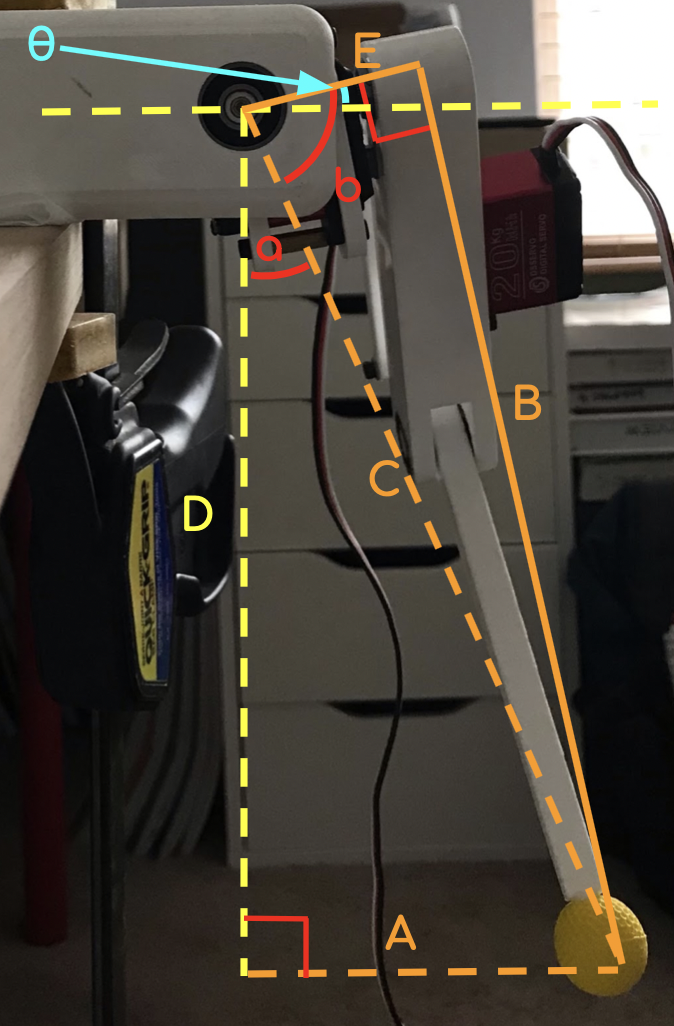
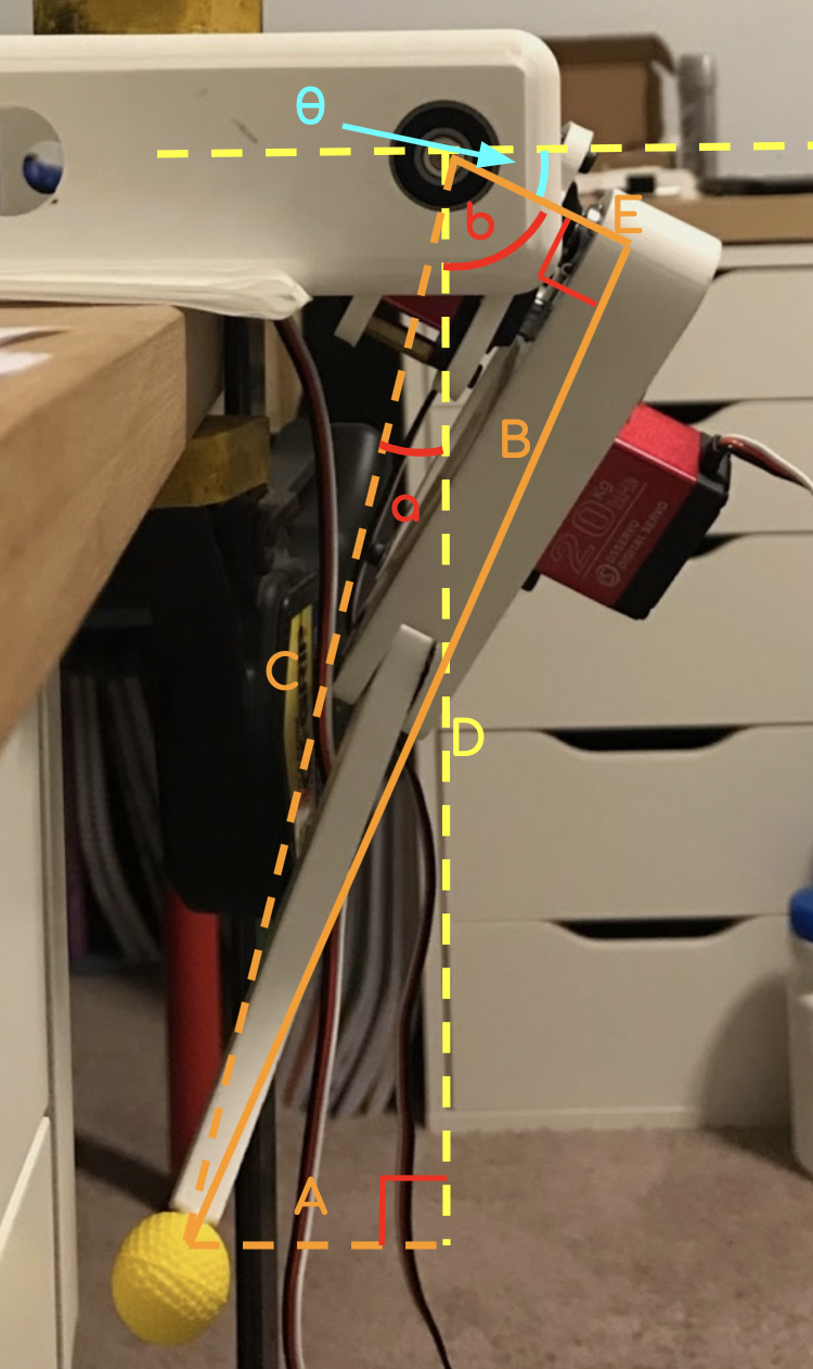
Yep, another degree of freedom! This time, it's to move the foot in the y-axis, or away from the sides of the body. The math for this stage is trigonometry again, however it is a bit more complex that before. This time, I'm going to use 2 diagrams to explain the math:
| Diagram 1: | Diagram 2: |
 |
 |
Inputs/outputs:
| Length A | Y Input |
| Length B: | Output |
| Length D | Z Input |
First, take a look at Digram 1. There are two things that need to be solved for: length B, which is the demand shoulder-foot length, and θ, which is the angle that needs to be sent to the motor to achieve the Y-axis input (specified by length A). To solve for B, you can take advantage of the two triangles that are formed; use A and D to solve for C with the pythagorean theorem: C = √(A2 + D2). C is the hypotenuse of another right triangle, so the pythagorean theorem can be used again: B = √(C2 - E2). Don't forget the E is constant (it is the actual length of the motor to the shoulder.
Now, here comes the tricky part. The method used to solve for B applies in all cases, but solving for θ is somewhat case-dependent. Firstly, note that I've defined the "𝟎" position of the foot (when A = 𝟎) to be under the bearing. When the foot is at 𝟎, it is actually tilted, and to get to be straight, A must equal E. For diagram 2 to apply, A is actually defined as a negative value. Now, let's start: I'll initially be refering to diagram 1. First, solve for angle a (I refer to this as theta in my code). This can be accomplished by any trigonometric function (since all sides are known and C considers the other lengths appropriately) but I chose to use tangent: tan(a) = ( A / D ) , or a = tan-1( A / D ). Now, skip over to solve for b (note that I call this alpha in my code). b can be solved easily with cosine: b = cos-1( E / C ). This is the part that requires insight: angles a and b add up to form an angle which (in the case of diagram 1) is greater than 90°; the part not covered by the 90° angle formed by the yellow lines is θ. When A becomes less than E, however, (a + b) is less than 90°; in this case, θ = 90° - (a + b). Isn't that cool?
So what if A is less than 𝟎? Refer to diagram 2: notice that a and b overlap (and don't worry, b will always be greater than a... yes, I checked) and θ now partly forms the 90° angle. In this case, θ = 90° - (b - a). Both cases can be summed up like here:
| If A > 0: | θ = abs(90° - (b + a)) |
| If A < 0 | θ = abs(90° - (b - a)) |
| If A < E: | θ = -1 ✖️ θ |
Here's the end result!
But there is one more thing to consider: what happenns to B? Well, B is simply passed on to the other stages of the program as the z-axis input. It gets inputted into the stage that considers the x-axis, which outputs its own z-axis to the final stage that calculates the z-axis motor angles. This can be done because B is the x-axis output on a new, tilted plane ( if A is ever specified, the whole leg tilts inward right?); the Y plane. All other stages lie on this plane.
Confusing? That's because it is. This entire stage took me nearly a month of designing, only to find out that my algorithms were wrong. This design I crunched out on a Tuesday night after finishing my Calculus homework. Soon, I'll have another post will all my failed ideas; why they didn't work, or why I abandoned them (I had a really cool idea involving tangent lines and derivatives).
Anyway, here's the code. Note that I refer to a as theta and b as alpha, and I've created a function solveFootPosition to organize all the stages/calculations.
The big stuff from this post is held in solveYMove.
void Kinematics::solveFtShldrLength(float demandFtShldr, float *demandAngle2, float *demandAngle3) {

  float _demandFtShldrLength = demandFtShldr;
  if (_demandFtShldrLength > SHOULDER_FOOT_MAX)
    _demandFtShldrLength = SHOULDER_FOOT_MAX;
  else if (_demandFtShldrLength < SHOULDER_FOOT_MIN)
    _demandFtShldrLength = SHOULDER_FOOT_MIN;

  // Use the Law of Cosines to solve for the angles of motor 3 and convert to degrees
  float _demandAngle3 = acos( ( pow(demandFtShldr, 2) - pow(LIMB_2, 2) - pow(LIMB_3, 2) ) / (-2 * LIMB_2 * LIMB_3) ); // demand angle for position 3 (operated by M3)
  _demandAngle3 = ((_demandAngle3 * 180) / PI);   //convert to degrees

  // Use demandAngle3 to calculate for demandAngle2 (angle for M2)
  float _demandAngle2 = ((180 - _demandAngle3) / 2 );

  *demandAngle2 += _demandAngle2;
  *demandAngle3 += _demandAngle3;
};


void  Kinematics::solveXMove(int16_t inputX, int16_t inputZ, float *demandAngle2, float *demandFtShldrLength) {
  if (inputZ == 0)
    inputZ = 1;   // you can never divide by 0!

  *demandFtShldrLength = sqrt(pow((float)abs(inputZ), 2) + pow((float)abs(inputX), 2));

  *demandAngle2 = ((atan((float)abs(inputX)/(float)abs(inputZ))*180) / PI);

  if (inputX > 0)
    *demandAngle2 *= -1;            // change later: make it negative if inputX is in the negative direction and parse it later
};


void Kinematics::solveYMove(int16_t inputY, int16_t inputZ, float *demandAngle1, float *yPlaneZOutput) {
  float demandFtShldrLength = sqrt(pow((float)abs(inputZ), 2) + pow((float)abs(inputY), 2)); // foot-shoulder distance on y-z plane (L1 in diagram)
  *yPlaneZOutput = sqrt(pow((float)abs(demandFtShldrLength), 2) - pow((float)abs(LIMB_1), 2));

  // Here, theta is the angle closest to the axis of rotation in the triangle relating inputY and inputZ
  // Alpha is the angle closest to the axis of rotation in the traingle relating leg length output to LIMB_1 length
  float theta = (float)abs((((float)atan((float)inputY/(float)inputZ) * 180) / PI));
  float alpha = (float)(((float)acos((float)LIMB_1/demandFtShldrLength) * 180) / PI);
  if (inputY >= 0) {
    *demandAngle1 += (float)abs((float)90 - (theta + alpha));
  }
  else if (inputY < 0) {
    *demandAngle1 += (float)abs((float)90 - (alpha - theta));   // since both triangles (refer to drawings) have the same hypotenuse, alpha > theta for all inputY
  }

  if (inputY < LIMB_1)
    *demandAngle1 *= -1;

}


void Kinematics::solveFootPosition(int16_t inputX, int16_t inputY, int16_t inputZ) {
  float demandAngle1 = 0;
  float demandAngle2 = 0;
  float demandAngle3 = 0;

  float yPlaneZOutput = 0;  // this is the foot-shoulder distance on the y-z plane (L1 in diagram)
  float demandFtShldrLength = 0;  // this is the foot-should distance on the x-z plane and the final calculated length

  solveYMove(inputY, inputZ, &demandAngle1, &yPlaneZOutput);

  solveXMove(inputX, yPlaneZOutput, &demandAngle2, &demandFtShldrLength);

  solveFtShldrLength(demandFtShldrLength, &demandAngle2, &demandAngle3);

  // Round off demand angles
  demandAngle1 = lrint(demandAngle1);
  demandAngle2 = lrint(demandAngle2);
  demandAngle3 = lrint(demandAngle3);

  // Calculate final demand angles suited to motors by applying necessary offsets
  demandAngle1 += M1_OFFSET;
  demandAngle2 += M2_OFFSET;
  demandAngle3 = (M3_OFFSET - demandAngle3) + M3_OFFSET;

  // Constrain motor angles
  demandAngle1 = _applyConstraints(1, demandAngle1);
  demandAngle2 = _applyConstraints(2, demandAngle2);
  demandAngle3 = _applyConstraints(3, demandAngle3);

  // Set live motor angles to the newly calculated ones

  //motor 1:
  motor1.angleDegrees = demandAngle1;
  motor1.angleMicros = _degreesToMicros(motor1.angleDegrees, motor1.calibOffset);

  // motor 2:
  motor2.angleDegrees = demandAngle2;
  motor2.angleMicros = _degreesToMicros(motor2.angleDegrees, motor2.calibOffset);

  // motor 3:
  motor3.angleDegrees = demandAngle3;
  motor3.angleMicros = _degreesToMicros(motor3.angleDegrees, motor3.calibOffset);

};
Problems... so far:
So far, no problems! I've tested this many times, with different x, y, and z positions and the math has been correct every time (I can check with a ruler to see if my x, y, and z inputs are considered accordingly). I'm really proud of this setup, and hopefully it won't fail me in the future!
