Building the Robot!
Ready to see this thing finished?
Well, not finished... but from a physical perspective, it is!
About a week ago, I released v1.0 of QuadrupedKinematics, my kinematics library. The latest commit supported the new version of interpolation, which is much more accurate and stable. After that, there was little left to do with only one leg. It was time to put the robot together!
First I started assembling the legs. This is pretty easy, as there are only a few screws, but getting the bearing and axle in is a bit tedious.
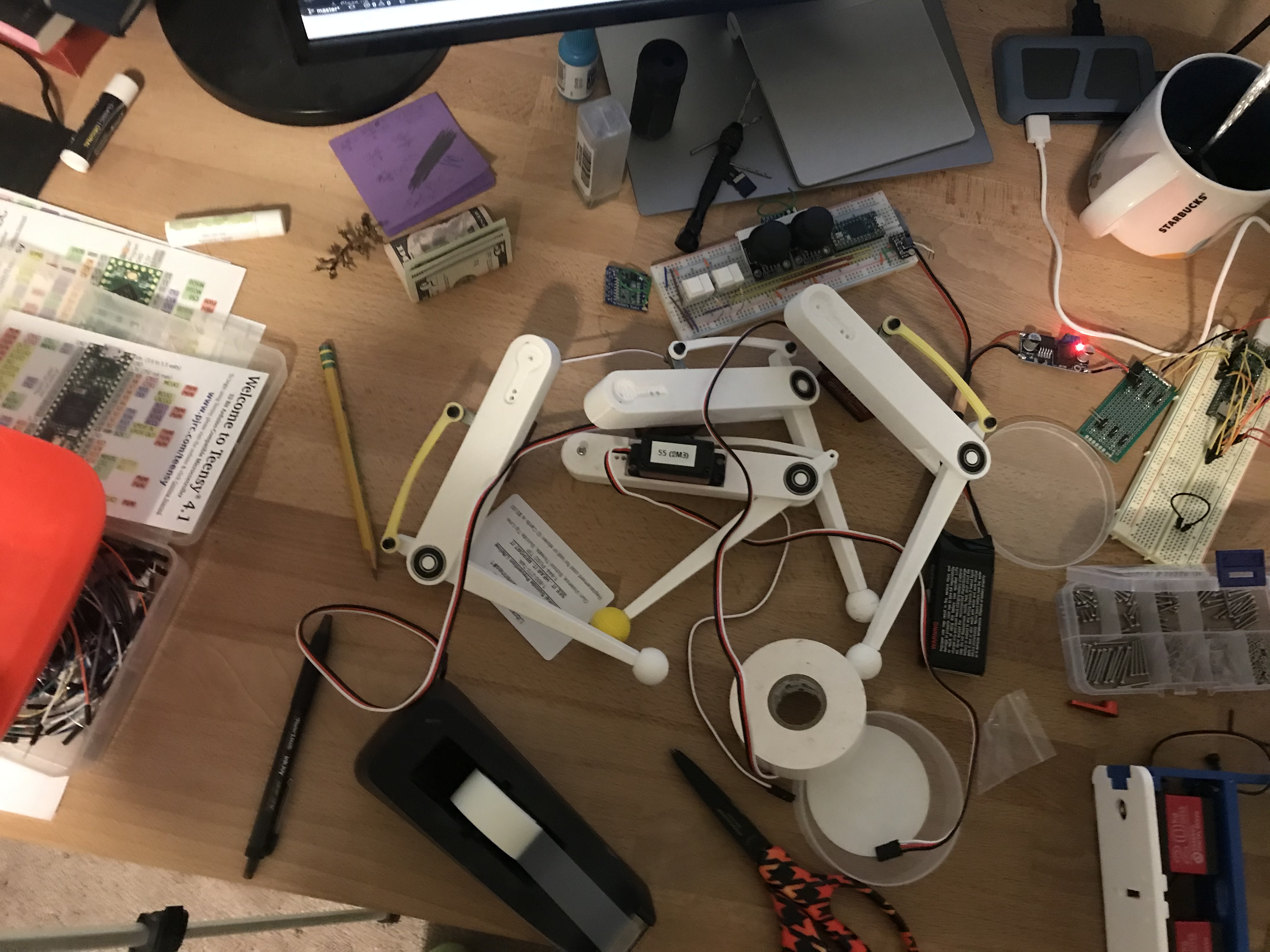
Next, I had to get the shoulder motors assembled. This took a really long time, because there are many screws and everything needs to be very tight. Additionally, I had to replace two after the 3d printed pars broke (I accidentally made the infill too low). Here you can see them next to my keyboard.
The chasis assembly (the big blue and white thing) was super simple. A bunch of m2 screws are required, but they were all easy to access and everything fit together well. The big blue piece saves some trouble too since it didn't need to be broken into smaller parts (it was a 12 hour print... the longest ever on my home printer!).
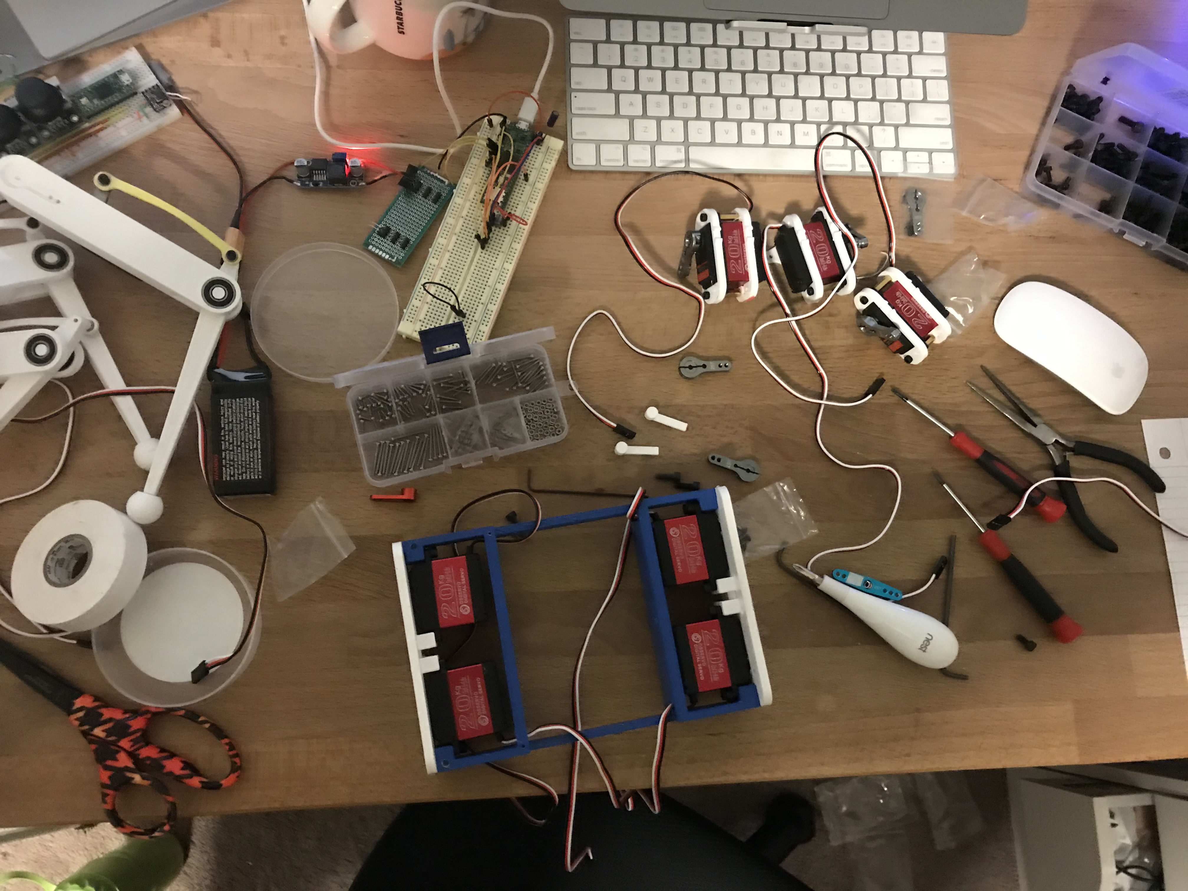
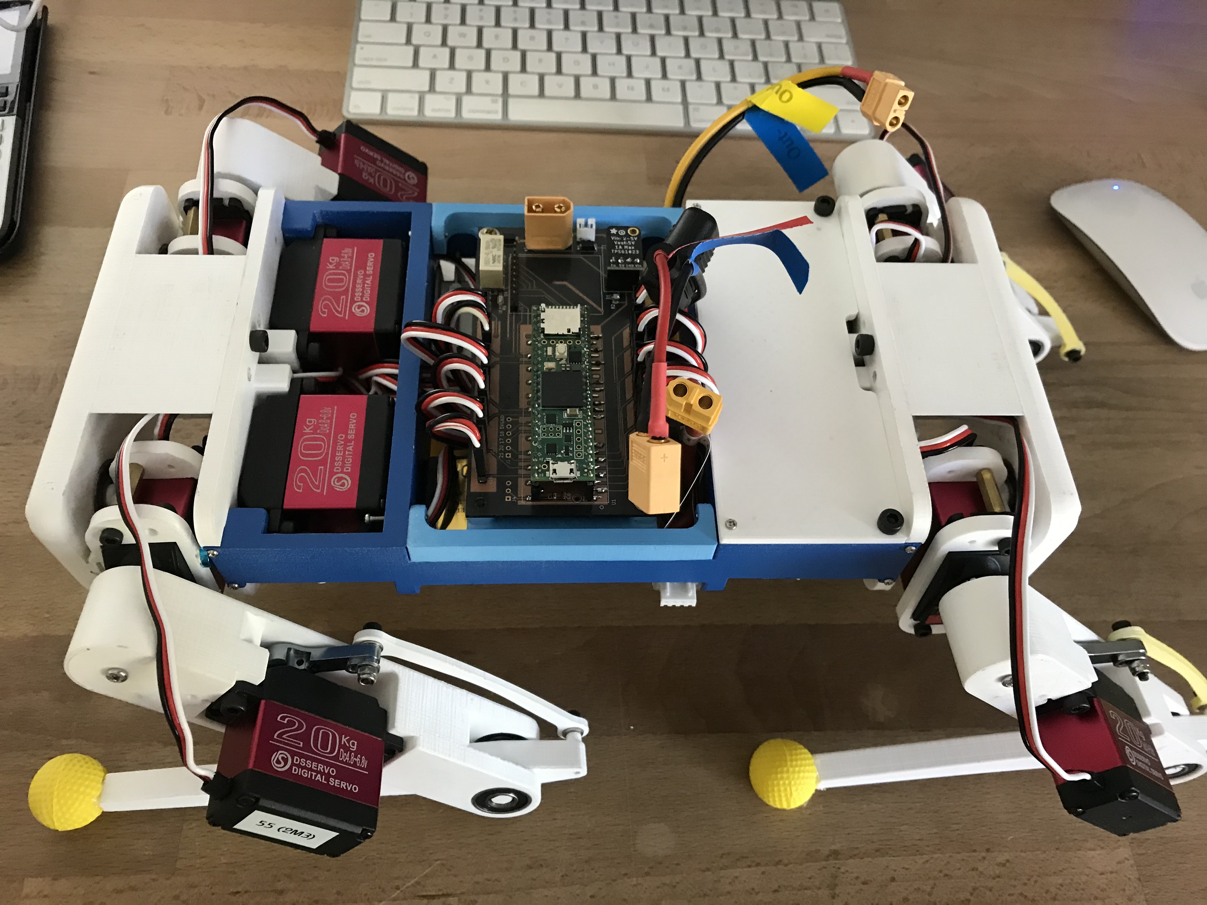
Eventually, I had almost everything assembled. The last part was the cabling, which took an unexpectedly long time; nearly an hour and a half.
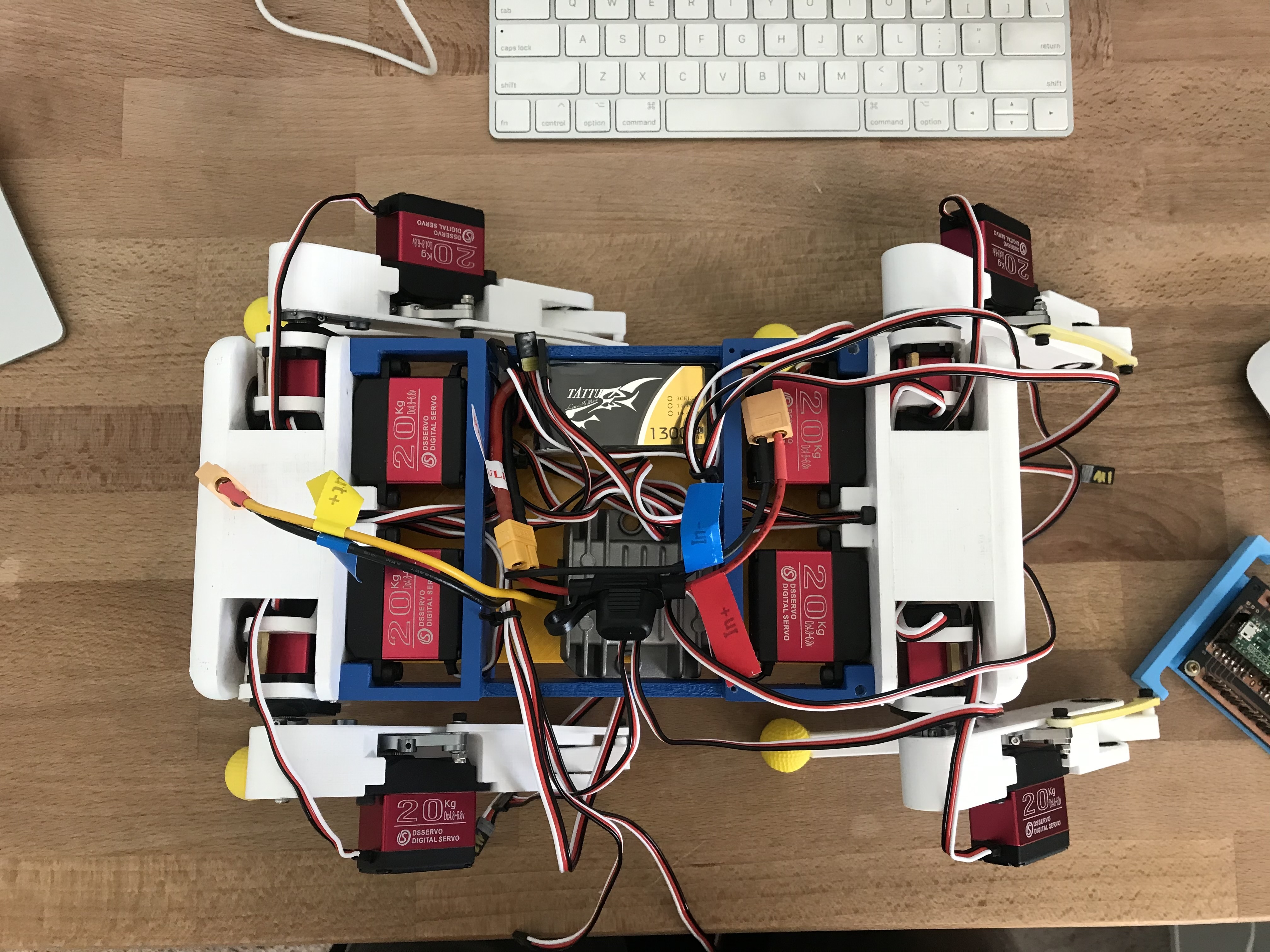
But in the end, I finished it! The entire assembly process took around 5 hours. One of the most important things to do during the build is the make sure that all the servo horns are in the right position. Since the servos can only turn 270 degrees and have a set 0 position, they increase in angle in different ways (very annoying) which means that the zero position for motors on the left side of the robot will be different than those for the right side. To make this easier, I used a really handy, super simple script so I could experiment with different zero positions:
#include <Servo.h>

Servo servo;

#define MOTOR_PIN           14
#define CALIB_OFFSET        20     // Calibration offset for each servo
#define DEGREES_TO_MICROS   7.5   // determined experimentally

int pos = 90;

void setup() {
  Serial.begin(9600);
  servo.attach(MOTOR_PIN);    // pin to hook your servo up to
}

void loop() {
  if (Serial.available()) {
    pos = Serial.parseInt();
    servo.writeMicroseconds(degreesToMicros(pos, CALIB_OFFSET));
  }
}

uint16_t degreesToMicros(uint8_t inputDegrees, uint8_t calibOffset) {
  int microsecondsInput = ((DEGREES_TO_MICROS * inputDegrees) + 500 + calibOffset);    // 500 is a "magic number" of micros for the motors; before that they do nothing
  return microsecondsInput;
}
It's really simple, but saved me lots of time!
I also made some electronic changes. Originally, I planned on using two 2s lipo batteries, one for the front and another for the back, to power the motors. Then I'd have 3A buck converters set up for each leg.
Later I realized this would be crazily annoying! Who wants to charge two batteries all the time? Also, each motor can draw a peak current close to an Amp... it's unlikely that all the motors in the robot will ever need to draw 1 amp and much more likely that all the motors in one leg will draw one amp. Thus, it's possible for one leg to draw too much current!
I decided to make everything simple by using a larger, 10A buck converter to power the entire robot. The one I'm using now converters 12V to 6V at 10A, which seems to be good. It also has a fuse, which the 3A ones didn't have. To get the 12V, I'm using a 1300mAh 3 lipo, which fits perfectly. 3s Lipos are rated for 11.1V at storage voltage, but simply charging it a little more brings it to 12V. A voltage drop of 1A isn't super critical anyway, since the buck converter is there to keep everything stable.
On board, there are 2 batteries. One dedicated to the motors (the 3s lipo), and the other (a 1s Lipo) just for the Teensy 4.1 and its peripherals (I have an LSM6DSOX IMU and LC709203F battery capacity guage on the PCB). I didn't know how to easily step down the 6v for the teensy/sensors... which I now do know how to do. With the next version, I'll try to make that work too!
I'm really pleased with this build! I also made a PCB for it, which I'll write a post about as soon as I can. Hopefully everything will be up and running soon!
You can find a complete bill of materials here.
Messy, much?
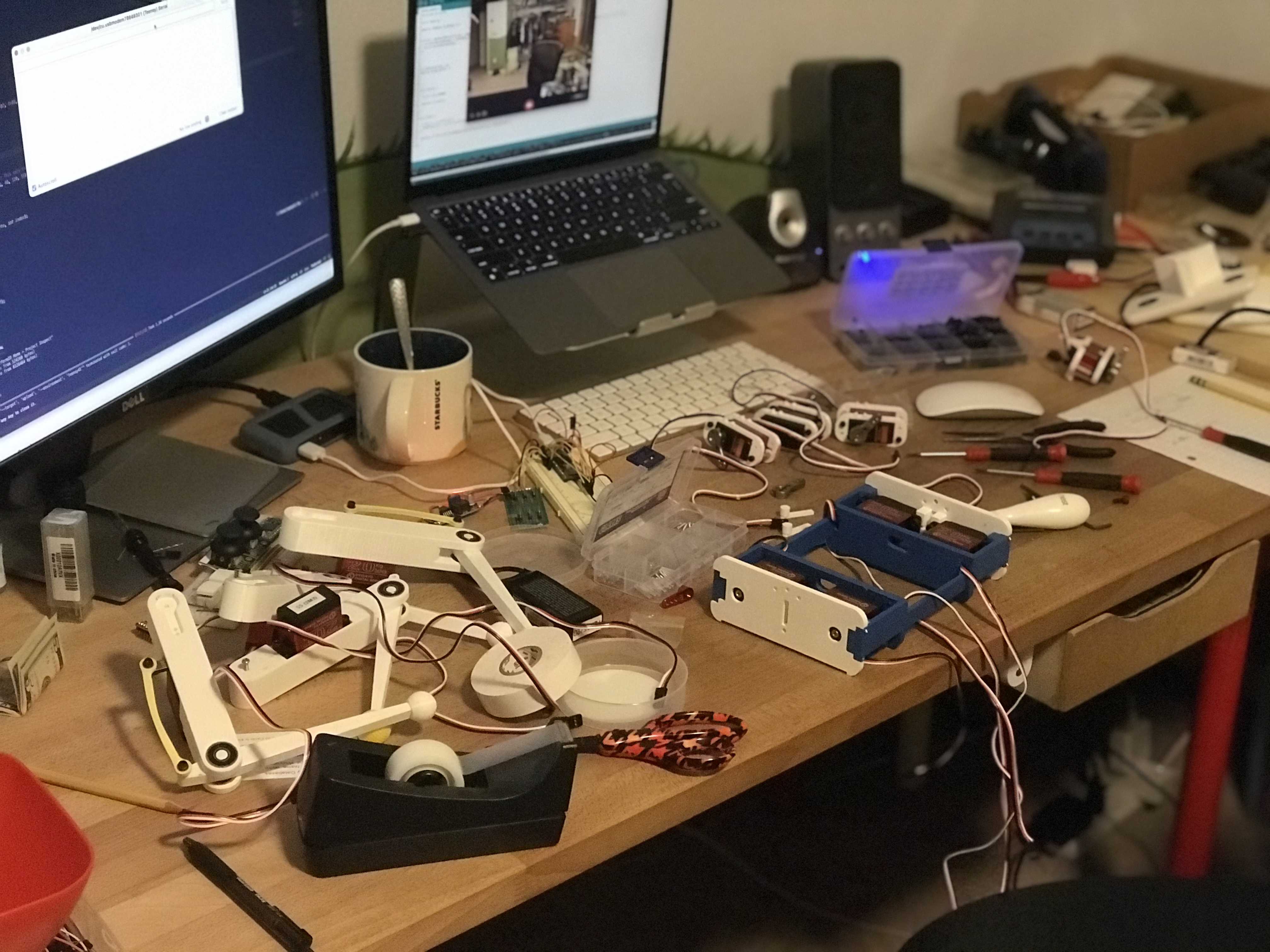 Final Product:
But wait! There's more!
The first thing to do was to verify that my wiring was correct. I spent a while organizing the wires and making sure that I knew which motor was for which wire, but it could still be wrong.
After I verified each motor's connection, I calibrated them and wrote a small program to drive each motor to the bot's stance position. The robot weighs 1.8kg (roughly) and each leg can carry around 1kg, so the robot should've been able to stand. After verifying everything, I got it to stand up unassisted!
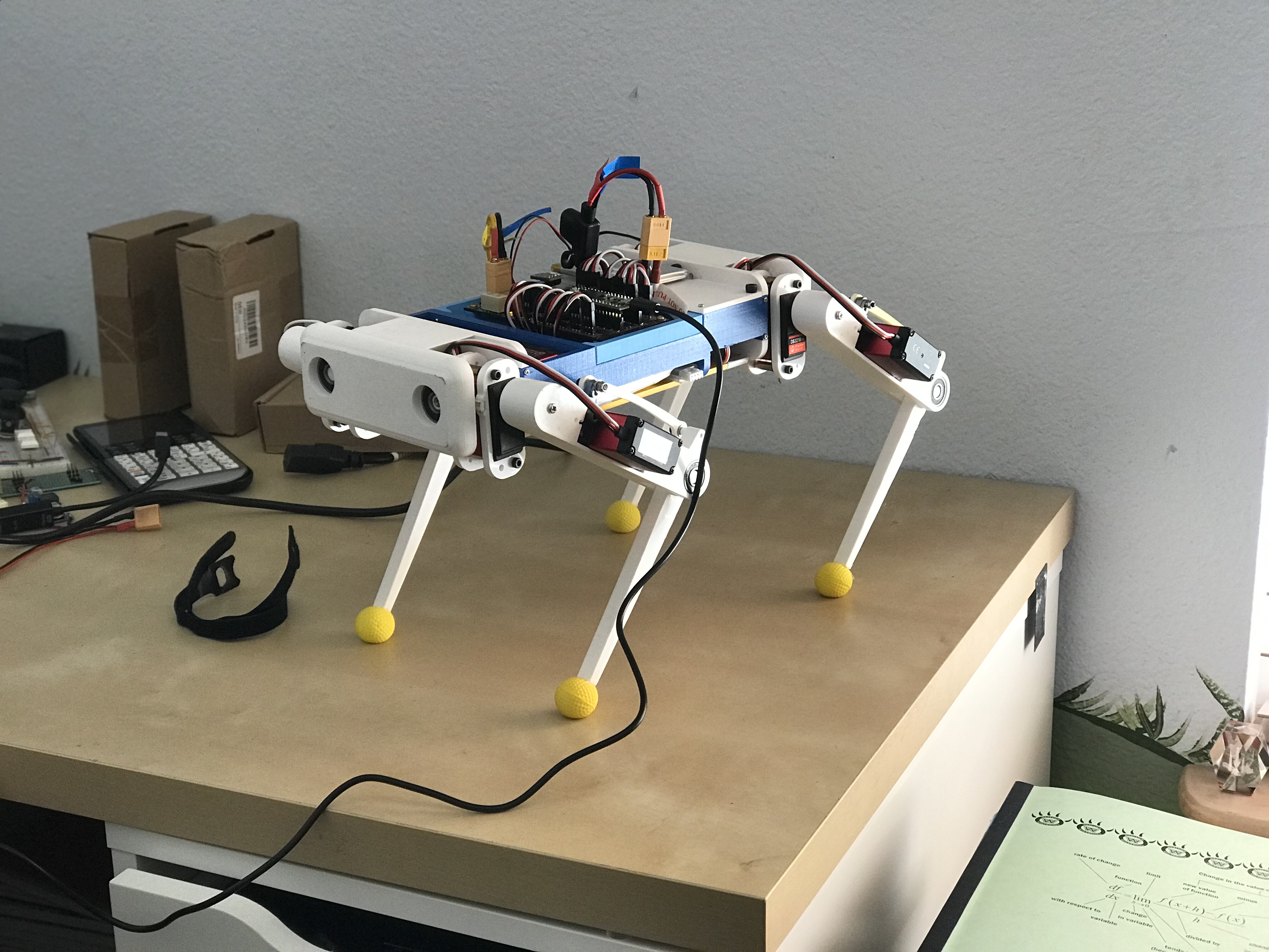
The next step was to get my kinematics library to work on this thing. This took a while; when I was originally writing the library, I wasn't sure how well I'd be able to implement the math and focussed on that instead of making a true library. This meant that I had some "magic" constants, but also that the calculation was speific to the leg I was working on. Each motor on each leg has a maximum point and minimum point that it can achieve before it starts to damage the hardware, for example. The biggest issue with this that the robot is mirrored on each side, and the motors have a defined (unchangeable) zero position with a 270 degree turn radius in a defined direction. That means that the position of the servo horn moving the leg joints need to be flipped to counteract the motors being flipped. Additionally, since the motors turn 270 degrees in a defined way, increasing the angle on one side of the robot may result in a movement equivalent to decreasing the angle for another motor on the other side. This is a big problem.
I decided to solve it as cleanly as I could by making the library general and interact with the main program as little as possible (something you should do for all libraries).
I did it by creating an array of struct variables:
// In Kinematics.h

typedef struct {
  uint8_t controlPin;

  // Angle/calculation stuff
  int16_t angleDegrees;
  int16_t previousDegrees;     // previous degrees since last call to updateDynamicPositions()
  int16_t dynamicDegrees;

  // Calibration
  uint16_t calibOffset;         // This is an offset for calibration (to keep the motor accurate)
  uint16_t maxPos;
  uint16_t minPos;
  uint16_t applicationOffset;   // This is an offset for putting the calculated angles in contex.
                                // It is likely that the zero positions of the motors isn't where
                                // calculations assumes it to be, so you need an offset to make
                                // sure that the angle is correct relative to the motor's zero.
} Motor;

// In motorSetup.h
Motor motors[ROBOT_LEG_COUNT * MOTORS_PER_LEG]; // ⬅ which gets defined with a bunch of motor structs later.
Now I can pass the array of motors to each leg object, and a parser inside the class determines the index of each motor in the array. Not does it allow you to use the exact same calculation functions for each leg despite having differnt offsets or constraints, but it's also super easy.
To make sure that the motors are set up correctly, I just use the applicationOffset variable and the knowledge of which
motor is being used to determine the correct position for each motor. It comes down to this:
switch (contexType) {

  case M1_standard: angle =  _motors[indexOfMotor(legID, motorID)].applicationOffset + angle; break;
  case M1_mirrored: angle =  _motors[indexOfMotor(legID, motorID)].applicationOffset - angle; break;

  case M2_standard: angle =  _motors[indexOfMotor(legID, motorID)].applicationOffset + angle; break;
  case M2_mirrored: angle =  90 - demandAngle; break;

  case M3_standard: angle = (2 * _motors[indexOfMotor(legID, motorID)].applicationOffset) - angle; break;
  case M3_mirrored: angle =  angle; break;
}
Constants ending in _standard signify motors whose final angles should be determined like leg2. _mirrored
constants signify motors that are the opposite of those in motor 2.
Since the calculations are the same for all the legs, you can now perform all the calculations... on all the legs!
It's hard to get into it here without plunking down a bunch of code, but it'll make a lot more sense if you just check out the file on github here. It's super simple!
Problems:
None, so far! Since the library's API is completely different, I released this as version 2.0.0. I haven't found any problems yet (hopefully there isn't room for many because the actual calculation is the same?).
That's all for now!
