Now that the hardware for the V2 5.8GHz radar is finished1, I’ve started thinking about designing a VNA. Looking back at my EE career, I think the key enabler was having access to electrical test equipment early on. To that end, since I didn’t have rf test equipment accessible to me, it took a while to get into that. A cheap VNA that can span frequency range of most affordable COTS components (typically ~5.8GHz due to prevalence of wifi band) would be super helpful, and it’s also a cool project to work on.
LibreVNA is a cool open-source 6Ghz VNA, based on Henrik’s original design from a few years ago. Unfortunately, 6Ghz doesn’t comfortably span wifi band - it’d be nice to have something a few GHz higher. The hard limitation in frequency range is set by the frequency synthesizer (most only support up to around 6Ghz, like the LMX2491, which I used for the radar), and the only one I’ve found that makes any significant jump is the LMX2495, a 15GHz synthesizer. Thus, I’m designing a 15Ghz VNA.
Recently, Henrik also made a 15GHz VNA, but to keep it affordable, most of his components didn’t actually span wide bandwidth (mixer for instance, only rated to 6Ghz), thereby likely giving him bad stability2 at anything past that3. The mixer performance is particularly constraining to the design because its conversion loss directly affects dynamic range and they also tend to be expensive relative to other components in the rf frontend.
Problem is that 100MHz-15GHz is kind of a weird frequency range, and there aren’t many mixers that satisfy that and stay affordable. Instead, some mixers span a wide bandwidth but are a bit shifted, so I need to see how degraded the performance is outside the reported bandwidth. Though mixer options are pretty limited, I opted for ones that are closer to the upper end of the band. In general, high frequency cutoff is limited by device parasitics, while low end is limited by balun rolloff. Thus you can actually improve low frequency behavior with small external inductor to increase magnetizing inductance, while you can’t do anything about high frequency performance.
Mini circuits stands out for having the most affordable options. Specifically, the mixers I want to test are:
| Reported Bandwidth | Expected L | Nominal LO | Cost($) | |
|---|---|---|---|---|
| MAC-12G+ | 3.8–12 GHz | <6 dBm | 7 dBm | ~44 |
| MDB-24H+ | 5–21.5 GHz | <11 dBm | 15 dBm | ~20 |
| SIM-24MH+ | 7.3–20 GHz | <5.7 dBm | 10 dBm | ~20 |
Test setup
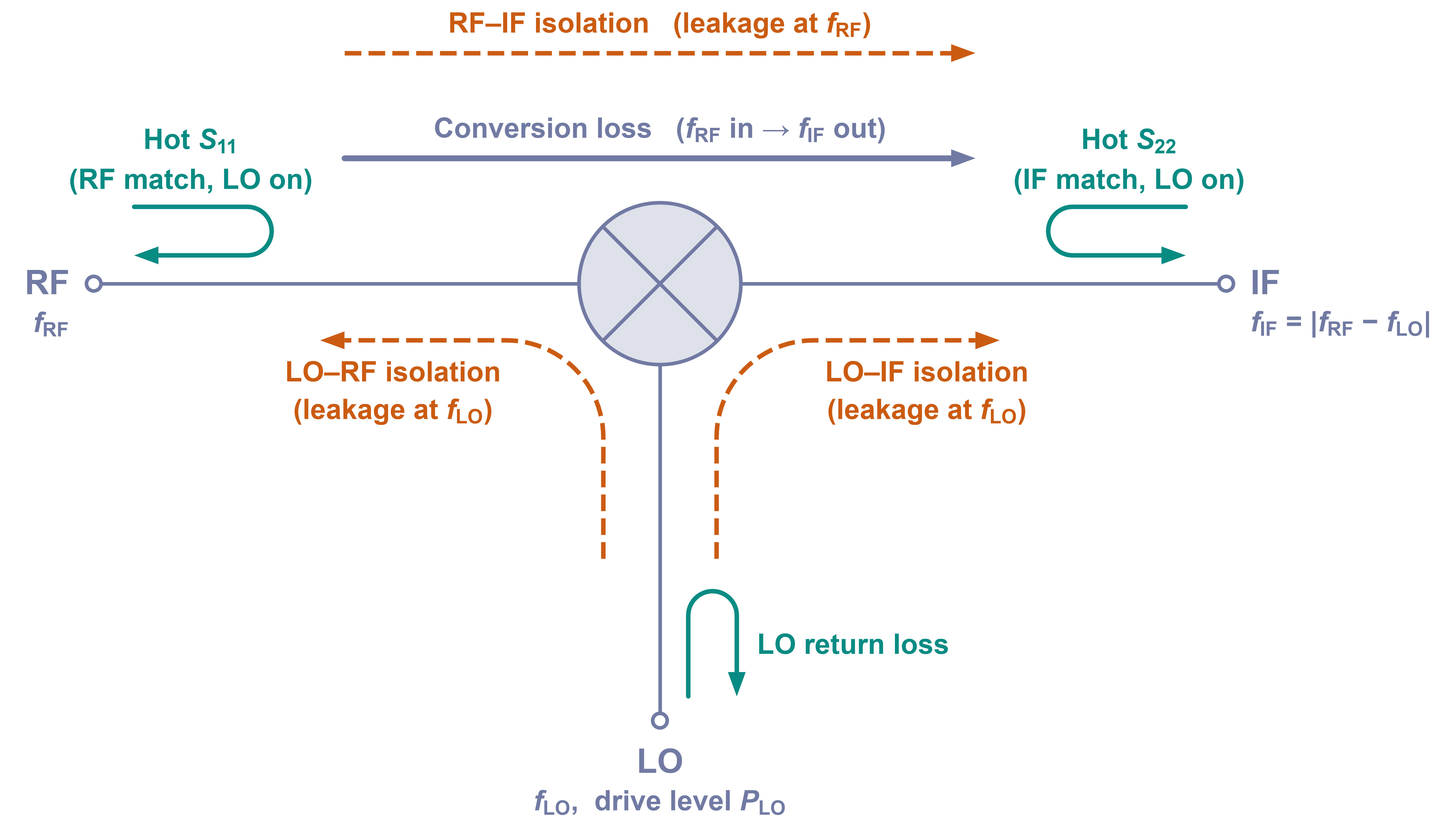
A mixer’s bandwidth is primarily defined by its band of acceptable conversion loss. Conversion loss both reduces your input signal power (so downstream IF amplifier needs to do more boosting) and is roughly equal to noise figure (so high loss is highly noisy) when single sideband is used. Though it’s impractical to estimate what ‘too much’ conversion loss really means - that defines the ‘stability,’ which is highly dimensional - it’s safe to say that under 20dB is usable. We’re also looking for fairly flat conversion loss, ideally. Other important parameters are isolation and hot reflection coefficient, but these can be ammended externally with padding.
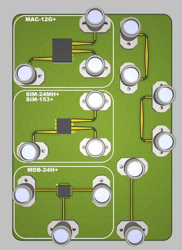
Coupon for this board is pretty simple, basically just broke out the three ports on each mixer to connectors. I got really nice screw-on 2.92 connectors from svmicrowave, should be more cost-effective than soldering a bunch of smas. Right side of the coupon has 2xthru FIX-FIX structures for deembedding the launch. To get everything to fit, I put 90 degree bends in with klopfenstein tapers to fix mismatch between trace width sizes.
Testing
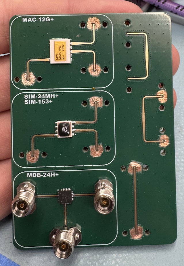
Once school started, I got it all soldered up:
Deembedding
I was in a bit of a rush making this coupon, so there were a few mistakes in the connector launch. For one, I forgot to remove the soldermask under the connector ground, so I had to do a bunch of scratching. On top of that, the connector footprint / launch ended up being really bad (copied datasheet instead of simulating because I didn’t have ansys). Take a look at the extracted fixture for the MDB (qfn package on the bottom):
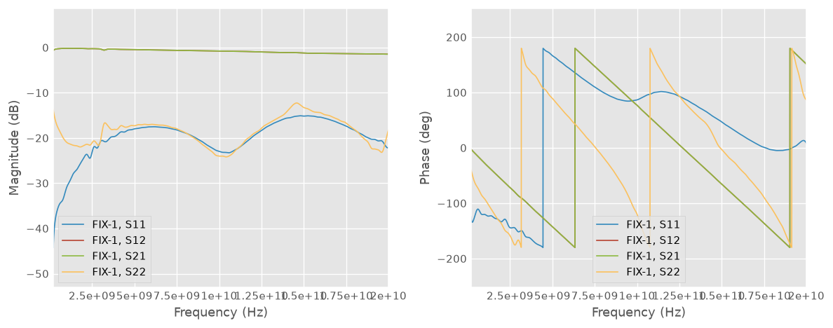 Bad fixture for MDB part
It’s not even below -20dB return loss, looking at S11. S22 trace going up in return loss at low frequency is effect of bad ground connection on the connectors - I fixed this for real measurements. The fixture gets even worse for the ones with the 90 degree bend and tapers, like the MAC fixture (white chip at the top of coupon):
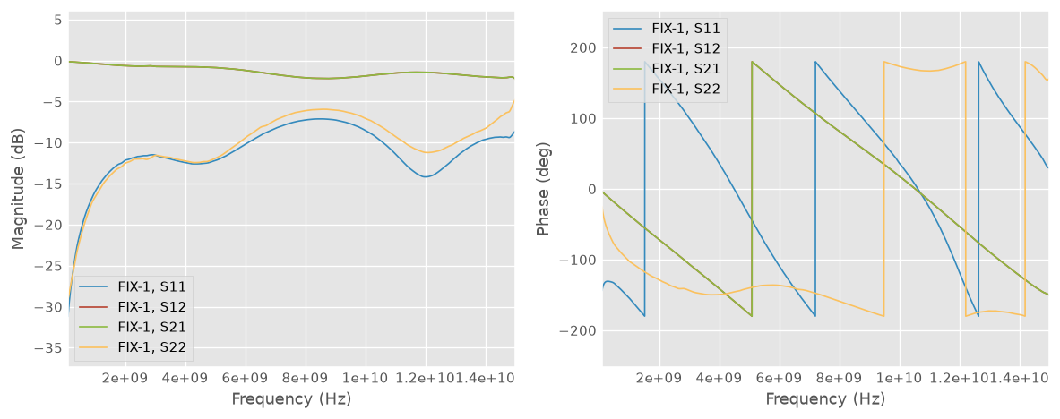
It’s horrible! I ended up simulating the launch (no bends or tapers) in hfss (I got ansys license again once back on campus), here’s the sim:
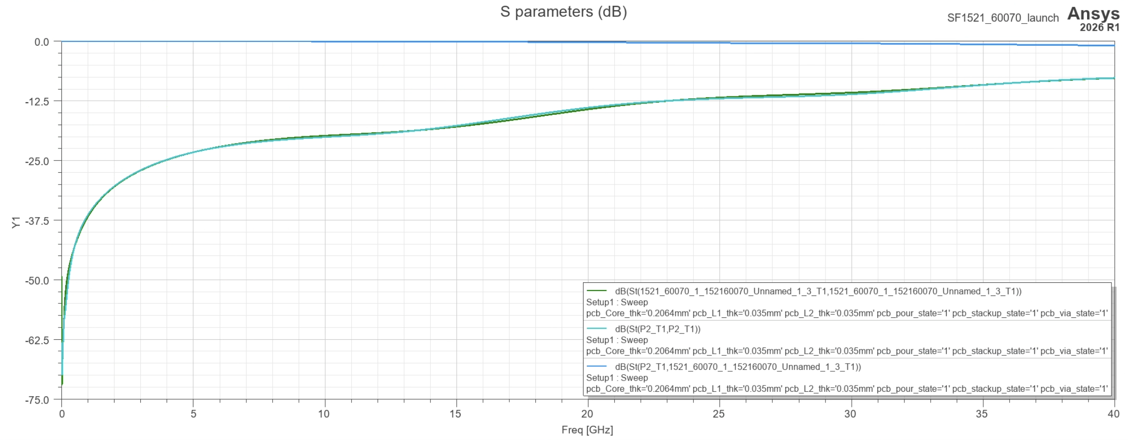
It sucks.
Interlude: debugging the launch
Looking at TDR, the reason it sucks is pretty obvious:
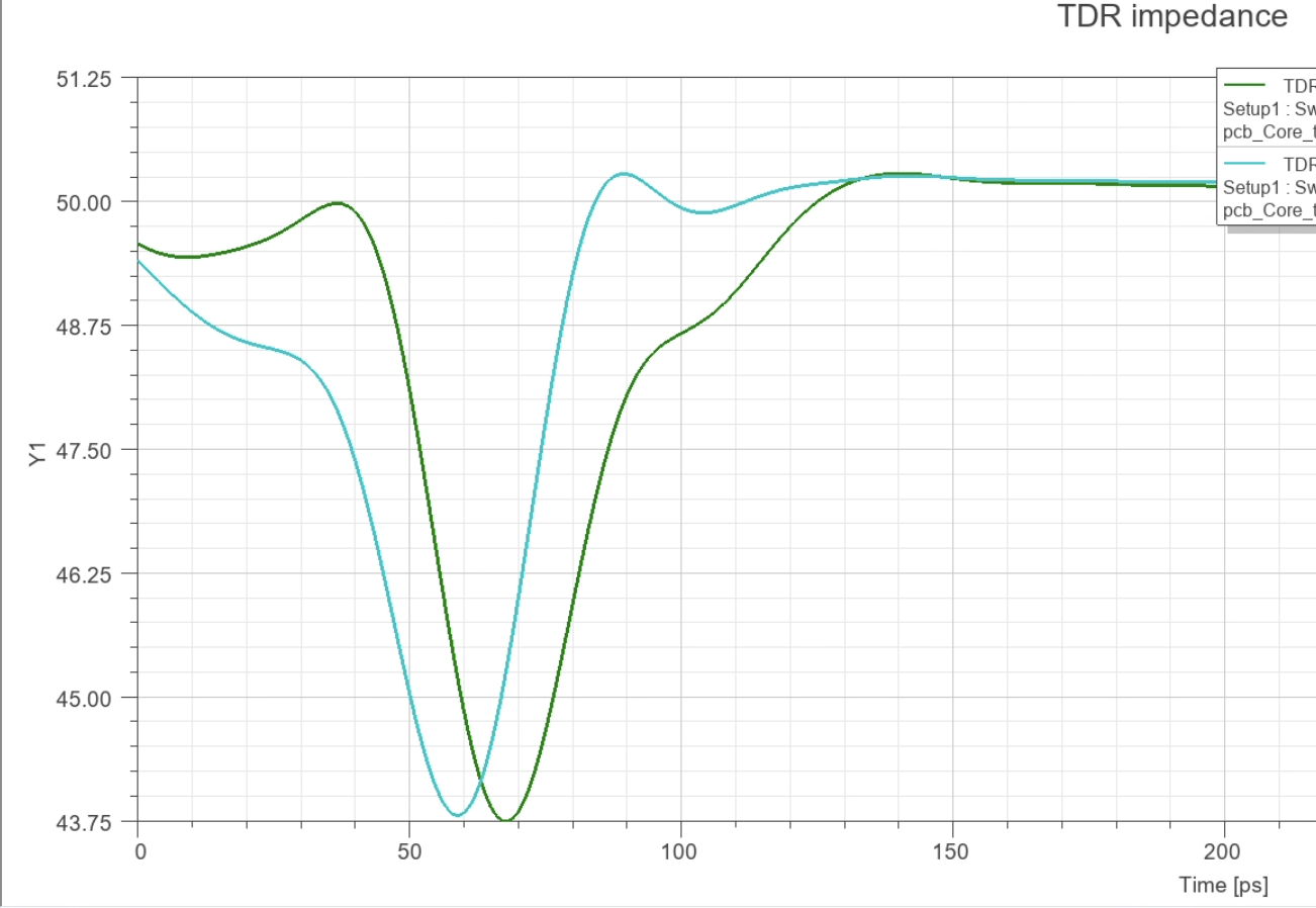
Big capacitance at the launch. With a round cutout under the launch pad, things look much better:
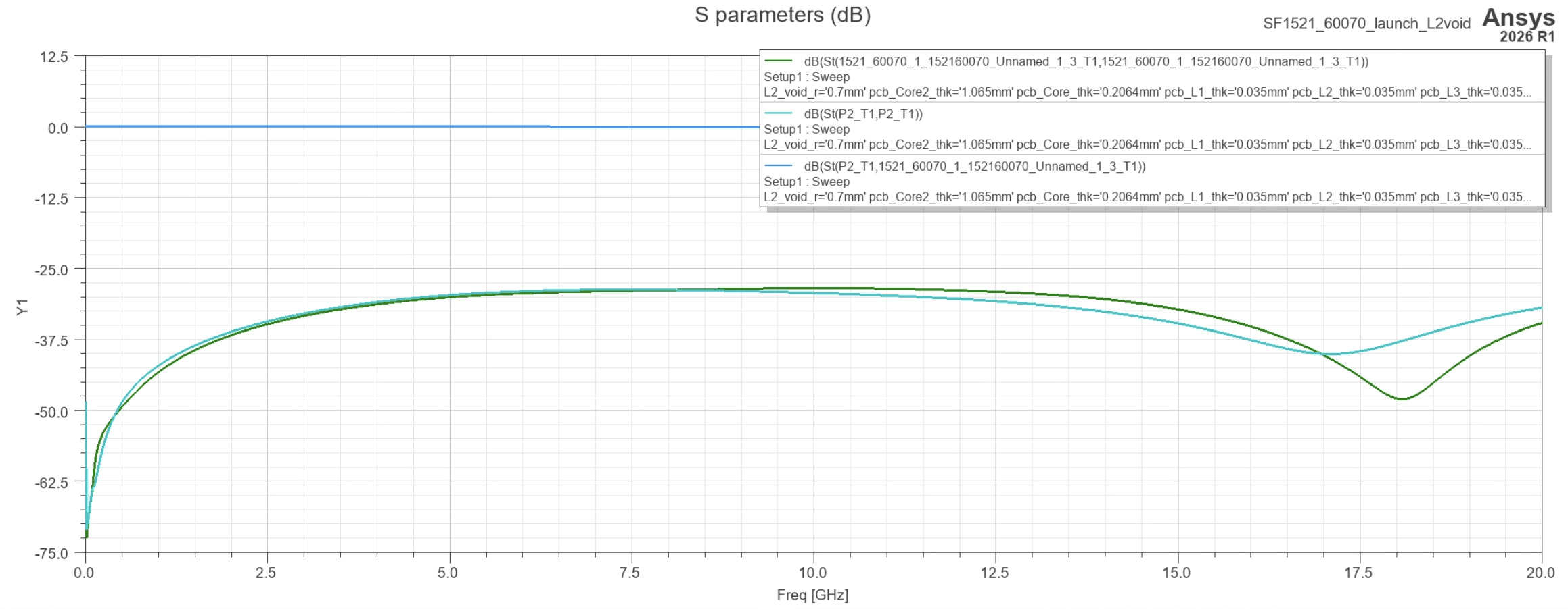
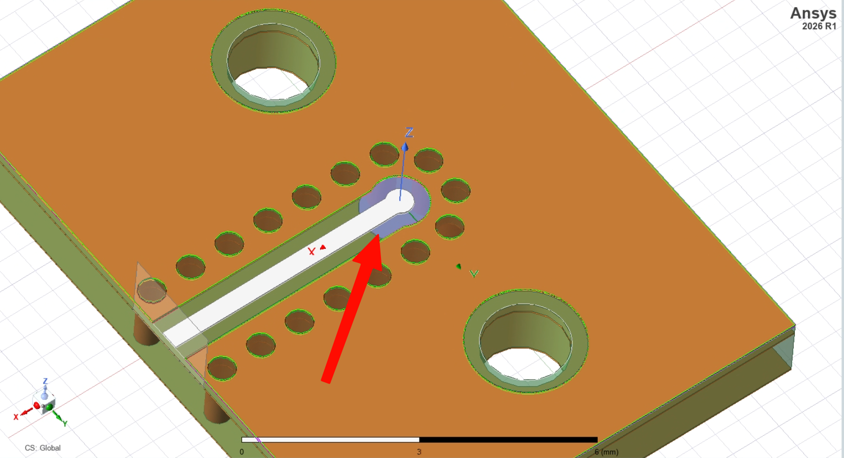
I’ll fix this on future boards.
Future Sean here - measurements on improved launch are in fact much better
That said, deembeding residuals were pretty low, so meausurement quality should be permissible.
Measurements
I made all these measurements on a ZNA-67, a 4-port 67Ghz VNA from R&S (I am very spoiled). Measuring mixer parameters requires stimulating and measuring ports at different frequencies though, which requires the ZNA-K4 frequency conversion software package. I was able to get a free trial for this, which saved a lot of headache.
Conversion Loss
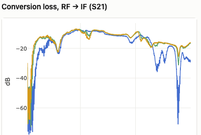
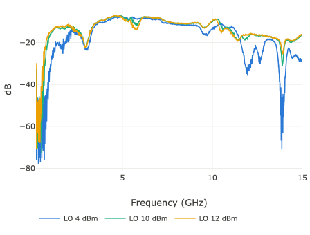
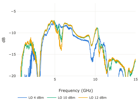
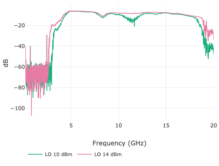
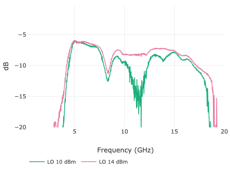
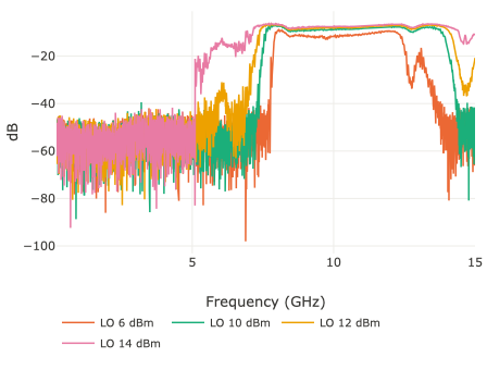
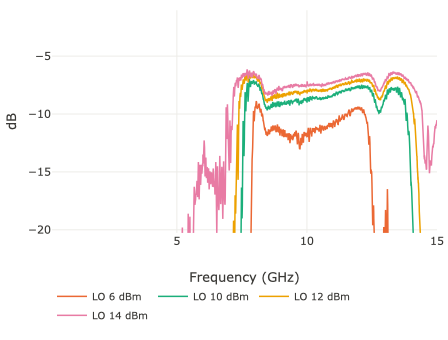
Here’s the raw measured conversion loss for each mixer, with a zoomed in version next to it:
MAC-12G+
MDB-24H+
SIM-24MH+
Almost immediately you can see that my original question is now answered: only the MAC-12G+ stands a practical chance of working. At the highest LO I measured for each, conversion loss for the MDB-24H tanks after 3GHz, SIM-24MH tanks after 5GHz. MAC-12G+ gets to around 800MHz at 20dB. Conversion loss of the MAC looks the worst, but it’s important to consider that the MAC pad launch is also the worst, and this hurts the conversion loss a lot; in reality you should correct for the pad by only computing loss by transmitted power. This can be ammeded by dividing by (subtracting in dB) by power transmission coefficient:
\[\text{-CL} = S_{21} - 10\log{1-|S_{11}|^2}\]Correcting for the pad mismatch brings the intrinsic conversion loss out from under the launch:
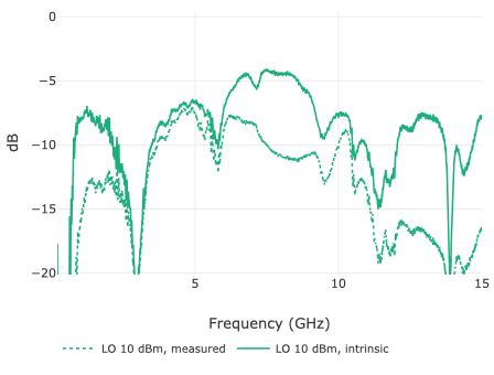
MAC-12G+, LO 10 dBm
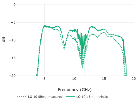
MDB-24H+, LO 10 dBm
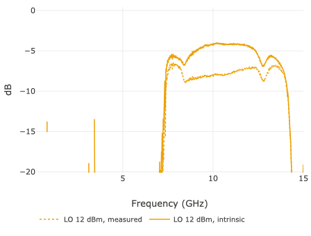
SIM-24MH+, LO 12 dBm
After correction MAC appears much better (though not as good as the others still - much measier spectrum). It also uses much lower LO which is nice.
Other thing to discuss is the odd 3GHz null in the MAC data, which is super weird. At first glance you would expect that the return loss is just poor there, but it remains after the S11 correction, indicating that the port is well matched. Assuming the mixer doesn’t actually have a null there (according to datasheet 3Ghz is out of band for the MAC), it’s as though the power disappears. Not really sure why this is yet, but will need to investigate more later.
I also measured a bunch of other stuff, like isolation and hot reflection coefficients, but these looked fine - similar to datasheet parameters, and usable for the vna. In particular, LO-RF isolation was generally under -20dB for all mixers, which is pretty good. Isolation to IF was also pretty good for all, but this doesn’t matter as much since IF will be filtered anyway.
P1dB
My VNA also had the gain compression package installed so I decided to measure P1dB on the MAC as well. Here is the measurement, with the S11 correction included as a trace as well:
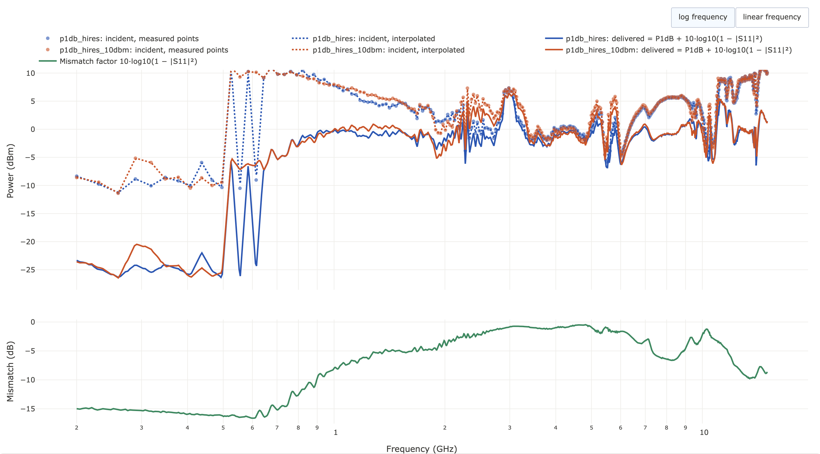
The datasheet says P1dB point is 1dBm, which appears to be nominally true, though there are some dips.
Other measurements
Normally there would be other interesting things to measure in the mixers like IIP3 and harmonic content, but these don’t actually matter for the VNA: IIP3 doesn’t apply because the DUT excitation is always single tone, and harmonic content at IF will get filtered by IF amp.
-
Still need to program it, but I wanted to get some hardware going for this first. Also still need to write post on the design, which I’ll do eventually… ↩
-
Stability here is defined as sensitivity of the circuit over time (primary aggressor being ambient temperature usually), so a device with low stability needs to be calibrated very often. Professional VNAs can last for months on a single calibration. ↩
-
In his post, he only looks at stability at 6GHz - the limit of his components. High frequency stability is probably much worse. ↩